


edge switch 2/16 service manual 4–7
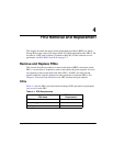
FRU Removal and Replacement
Replacement
To replace a cooling fan:
1. Remove the replacement cooling fan FRU from its shipping container.
2. Inspect the rear of the fan for bent or broken connector pins. If any pins are
damaged, obtain a new fan.
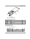
3. Position the fan FRU with its retaining screw at the upper right corner (the fan
cannot be inserted in any other position).
4. Push the fan FRU into the chassis to engage the connector pins until the fan
faceplate is flush with the chassis.
5. Engage the screw threads and lightly tighten the screw. Over-tightening the screw
may damage the FRU or chassis.
6. Inspect the fan FRU to ensure that the amber LED is extinguished. If the amber
LED is illuminated, go to "
MAP 0000: Start MAP
" on page 2-7 to isolate the
problem.
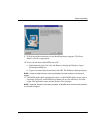
7. At the HAFM server’s Hardware View, select the Event Log option from the Logs
icon. The Event Log displays. Ensure one of the following event codes appears in
the log:
— 310 to 315 - Nth cooling fan has recovered, where N is first to fourth (fan).
8. At the HAFM server’s Hardware View, observe the fan graphic and ensure no alert
symbols appear that indicate a failure (yellow triangle or red diamond). If a
problem is indicated, go to "
MAP 0000: Start MAP" on page 2-7 to isolate the
problem.
9. Perform the data collection procedure (refer to "
Collecting Maintenance Data
" on
page 3-31).
10. Clear the switch system error (ERR) LED:
a. At the HAFM server’s Hardware View, right-click the front panel bezel graphic
(away from a FRU) to open a pop-up menu.
b. Click the Clear System Error Light menu selection.