


14 Installation
Chapter 2 - Hardware Installation
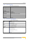
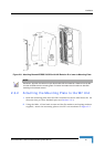
2.1.2 Top Panel
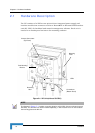
Figure 2-3 shows the top panel of the Wi² unit with two N-type RF connectors for
external antennas.
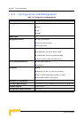
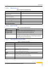
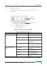
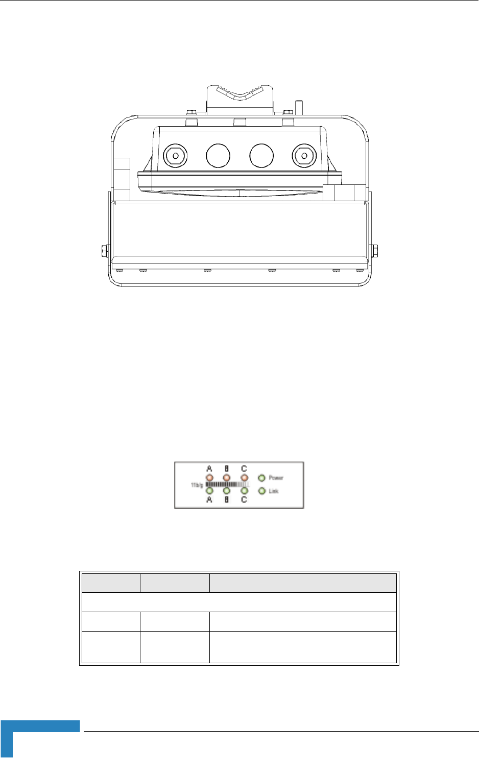
2.1.3 LED Indicators
The Wi² includes eight status LED indicators. Figure 2-4 shows the LEDs and
Table 2-2 describes the system status.
Figure 2-3: Top Panel (without the SU-ODU)
Figure 2-4: LED Indicators
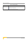
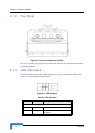
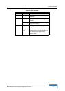
Table 2-2: LED Indicators
LED Status Description
11 b/g (three pairs of LEDs
A Always on
B Flashing Indicates packets received using 802.11b
modulation.