


126 PresentationPRO-II • User’s Guide
^K==péÉÅáÑáÅ~íáçåë
Pinouts
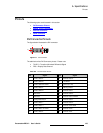
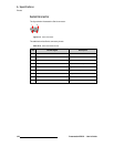
^å~äçÖ=NRJéáå=a=`çååÉÅíçê
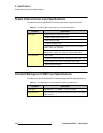
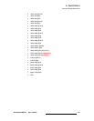
The figure below illustrates the analog 15-pin D connector:
Figure A-2. Analog 15-pin D Connector
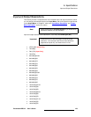
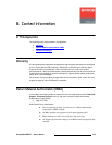
The table below lists Analog 15-pin D connector pinouts.
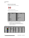
Note that each analog input connector accepts a variety of analog formats including VGA,
low-resolution composite video, S-video and YUV component video.
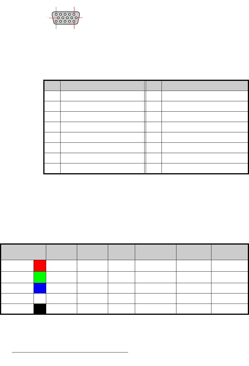
• For RGB with H and V sync, use the VGA connector directly.
• Using a (customer supplied) VGA to 5xBNC breakout cable, five input
combinations are possible. Cells with check marks denote the connections
required for the indicated format.
Table A-7. Analog 15-pin D Connector Pinouts
Pin Signal Pin Signal
1Red 9
2 Green 10 GND
3Blue 11
412
5 13 H Sync or C Sync
6 Red return 14 V Sync
7 Green return 15
8Blue return
10 6
51
15 11
Table A-8. Analog Input Combinations using Breakout Cable
Breakout Cable
Wire Color
Composite
Video
S-Video
(Y/C)
YUV
(YP
b
P
r
)
RGB
Sync on Green
RGB
Comp Sync
RGB
Separate H V
R
3 (Chrom)
3 (P
r
) 3 33
G
33 (Lum)
3 (Lum) 333
B 3 (P
b
) 333
H Sync 33
V Sync 3