


PresentationPRO-II • User’s Guide 25
3. Hardware Installation
Installation
fåëí~ää~íáçå
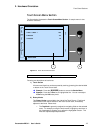
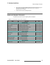
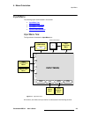
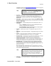
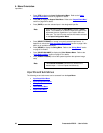
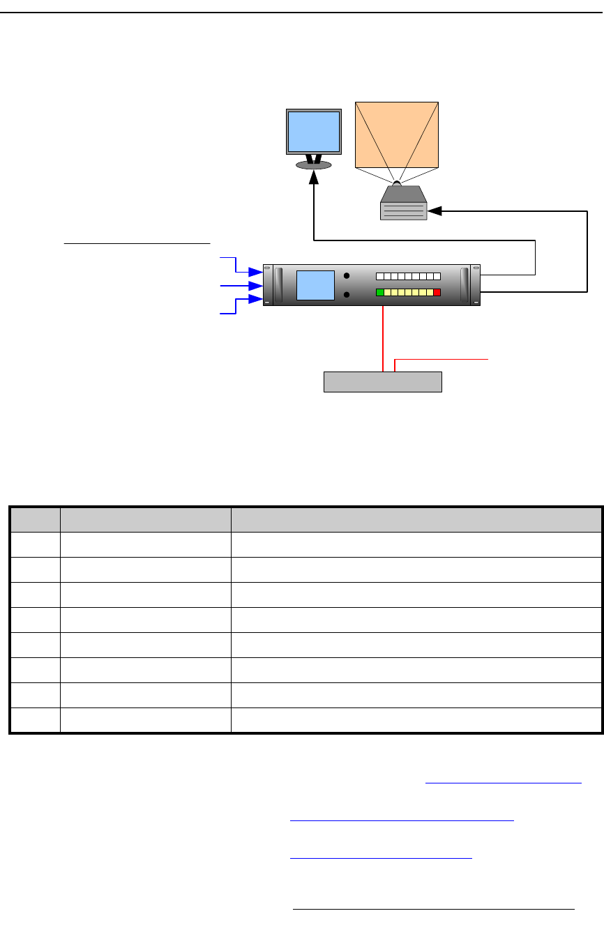
The figure below illustrates a block diagram of a basic PresentationPRO-II system. This
diagram can be used as reference in the following installation procedure.
Figure 3-1. Block Diagram, Basic PresentationPRO-II System
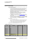
You will need:
Use the following steps to install PresentationPRO-II:
1. Follow the unpacking procedures as listed in the “Unpacking and Inspection”
section on page 22.
2. As required, refer to the “Physical and Electrical Specifications” section on
page 124 in Appendix A for electrical and mechanical details.
3. As required, refer to the “PresentationPRO-II Rear Panel” section on page 12 in
Chapter 2 for the locations of all connectors.
Ethernet Hub / Switch
Program Out (Analog)
Program Out (Digital)
Inputs
Projector
Program
To External
Controller
Ethernet
(Optional)
Analog Sources to Analog Inputs 1-8
SD-SDI Source to SDI Input (SDI Model)
SD-SDI/HD-SDI Source to SDI Input (HD Model)
DVI Source to BG/DSK Input
Table 3-3. Equipment List, Basic PresentationPRO-II System
Qty. Item Note
1 PresentationPRO-II Chassis
1 Video Projector and cable Customer supplied
1 Analog Monitor and cable Customer supplied
1 Ethernet Hub or Switch Customer supplied (Optional, with External Controller)
2 Ethernet cables Customer supplied (Optional, with External Controller)
1 DVI-DVI cable Customer supplied (for BG/DSK input)
1 Video cable Customer supplied (for SD-SDI or HD-SDI input)
TBD Dedicated sources Analog video as required (customer supplied)