


Chapter 4 Parameters|
4-52 Revision August 2008, 03VE, SW V2.04
Control
mode
VF VFPG SVC
Settings 230V series 0.1 to 255.0V Factory Setting: 0.0
460V series 0.1 to 510.0V Factory Setting: 0.0
01-41 4th Output Frequency Setting 2 Unit: 0.01
Control
mode
VF VFPG SVC FOCPG TQRPG
Factory Setting: 0.00
Settings 0.00~600.00Hz
01-42 4th Output Voltage Setting 2 Unit: 0.1
Control
mode
VF VFPG SVC
Settings 230V series 0.1 to 255.0V Factory Setting: 0.0
460V series 0.1 to 510.0V Factory Setting: 0.0
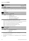
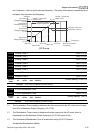
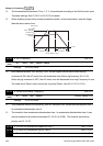
V/f curve setting is usually set by the motor’s allowable loading characteristics. Pay special
attention to the motor’s heat dissipation, dynamic balance, and bearing lubricity, if the loading
characteristics exceed the loading limit of the motor.
For the V/f curve setting, it should be Pr.01-01≥ Pr.01-03≥ Pr.01-05≥ Pr.01-07. There is no
limit for the voltage setting, but a high voltage at the low frequency may cause motor damage,
overheat, stall prevention or over-current protection. Therefore, please use the low voltage at
the low frequency to prevent motor damage.
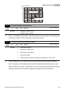
Pr.01-35 to Pr.01-42 is the V/f curve for the motor 2. When multi-function input terminals Pr.02-
01 to Pr.02-14 is set to 14 and enabled or switch to the Δ-connection, the AC motor drive will
act as the 2nd V/f curve.
01-09 Start Frequency Unit: 0.01
Control
mode
VF VFPG SVC FOCPG
Factory Setting: 0.50
Settings 0.00~600.00Hz
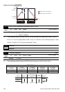
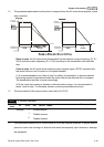
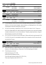
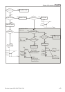
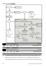
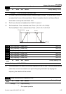
When start frequency is higher than the min. output frequency, drives’ output will be from start
frequency to the setting frequency. Please refer to the following diagram for details.
Fcmd=frequency command,
Fstart=start frequency (Pr.01-09),
fstart=actual start frequency of drive,
Fmin=4th output frequency setting (Pr.01-07/Pr.01-41),
Flow=output frequency lower limit (Pr.01-11)