


Chapter 4 Parameters|
4-154 Revision August 2008, 03VE, SW V2.04
4
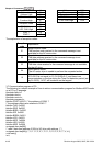
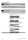
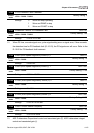
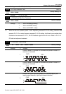
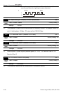
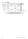
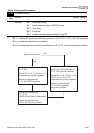
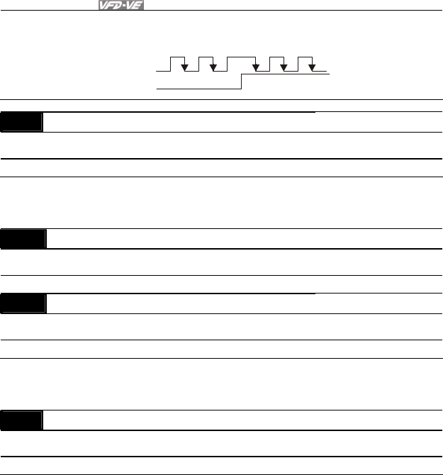
Phase A is a pulse input and phase B is a direction input. (low
input=forward direction, high input=reverse direction)
A
B
FWD
REV
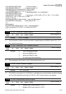
10-16 Output Setting for Frequency Division (denominator) Unit: 1
Control
mode
VFPG FOCPG TQRPG
Factory Setting: 1
Settings 1 to 255
This parameter is used to set the denominator for frequency division. For example, when it is
set to 2 with feedback 1024ppr, PG output will be 1024/2=512ppr.
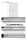
10-17 PG Electrical Gear A (Channel 1 of PG card) Unit: 1
Control
mode
VFPG FOCPG
Factory Setting: 100
Settings 1 to 5000
10-18 PG Electrical Gear B (Channel 2 of PG card) Unit: 1
Control
mode
VFPG FOCPG
Factory Setting: 100
Settings 1 to 5000
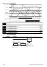
Rotation speed = pulse frequency/encoder pulse (Pr.10-00) * PG Electrical Gear A / PG
Electrical Gear B.
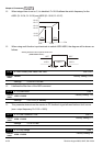
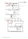
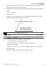
10-19 PG Position Control Point (Home) Unit: 1
Control
mode
VFPG FOCPG
Factory Setting: 0
Settings 0 to 20000
This parameter determines the home position in the position control.