


Chapter 4 Parameters|
Revision August 2008, 03VE, SW V2.04 4-93
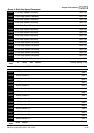
05-24 Torque Compensation Gain Unit: 1
Control
mode
VF VFPG
Factory setting: 0
Settings 0 to10
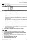
This parameter may be set so that the AC motor drive will increase its voltage output to obtain
a higher torque. Only to be used for SVC control mode.
Too high torque compensation can overheat the motor.
05-25 Slip Compensation Gain Unit: 0.01
Control
mode
VF SVC
Factory setting: 0.00
Settings 0.00 to10.00
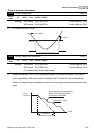
When the asynchronous motor is driven by the drive, the load and slip will be increased. This
parameter can be used to correct frequency and lower the slip to make the motor can run near
the synchronous speed under rated current. When the output current is larger than the motor
no-load current, the drive will compensate the frequency by Pr.05-25 setting. If the actual
speed is slower than expectation, please increase the setting and vice versa.
It is only valid in SVC/VF mode.
The factory settings are:
A. In SVC mode, the factory setting is 1.00.
B. In VF mode, the factory setting is 0.00.
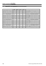
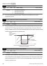
05-26 Slip Deviation Level Unit: 1
Control
mode
VFPG SVC FOCPG
Factory setting: 0
Settings 0 to 1000% (0: disable)
05-27 Detection time of Slip Deviation Unit: 0.1
Control
mode
VFPG SVC FOCPG
Factory setting: 1.0
Settings 0.0 to 10.0 sec
05-28 Over Slip Treatment
Control
mode
VFPG SVC FOCPG
Factory setting: 0
Settings 0 Warn and keep operation
1 Warn and ramp to stop
2 Warn and coast to stop