


Chapter 4 Parameters|
Revision August 2008, 03VE, SW V2.04 4-137
Group 9: Communication Parameters
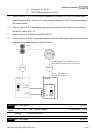
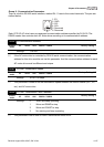
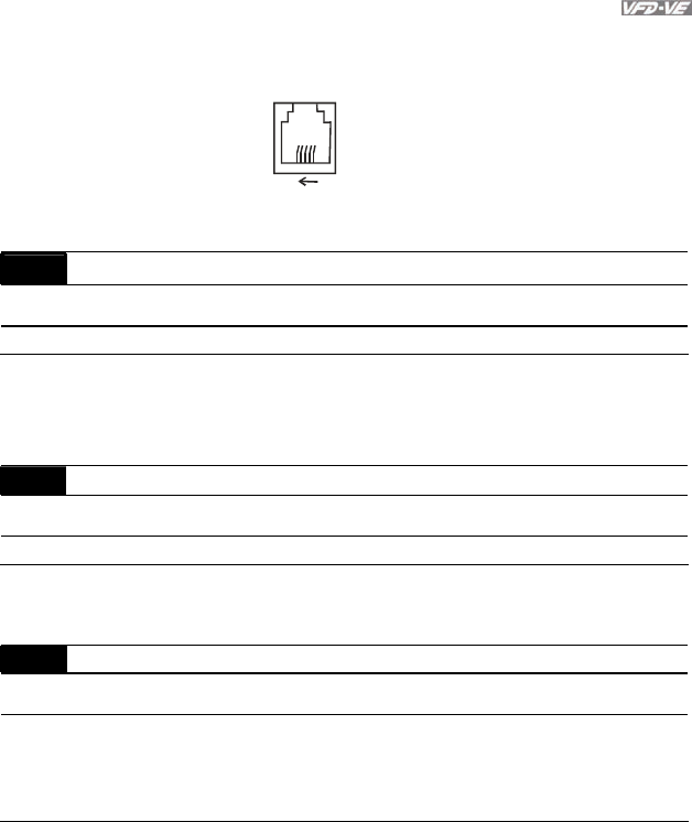
There is a built-in RS-485 serial interface, marked RJ-11 near to the control terminals. The pins are
defined below:
6
1
1: EV
2: GND
3: SG-
4: SG+
5: Reserved
6: Reserved
Each VFD-VE AC drive has a pre-assigned communication address specified by Pr.09-00. The
RS485 master then controls each AC motor drive according to its communication address.
09-00 Communication Address
Control
mode
VF VFPG SVC FOCPG TQRPG
Factory Setting: 1
Settings 1 to 254
If the AC motor drive is controlled by RS-485 serial communication, the communication
address for this drive must be set via this parameter. And the communication address for each
AC motor drive must be different and unique.
09-01 COM1 Transmission Speed
Control
mode
VF VFPG SVC FOCPG TQRPG
Factory Setting: 9.6
Settings 4.8 to 115.2kbps
This parameter is used to set the transmission speed between the RS485 master (PLC, PC,
etc.) and AC motor drive.
09-02 COM1 Transmission Fault Treatment
Control
mode
VF VFPG SVC FOCPG TQRPG
Factory Setting: 3
Settings 0 Warn and keep operating
1 Warn and RAMP to stop
2 Warn and COAST to stop
3 No warning and keep operating
This parameter is set to how to react if transmission errors occur.