


Chapter 4 Parameters|
Revision August 2008, 03VE, SW V2.04 4-119
Group 8 High-function PID Parameters
08-00
Input Terminal for PID Feedback
Control
mode
VF VFPG SVC FOCPG
Factory Setting: 0
Settings 0 No function
1 Negative PID feedback from external terminal AVI (Pr.03-00)
2 Negative PID feedback from PG card (Pr.10-15, skip direction)
3 Negative PID feedback from PG card (Pr.10-15)
4 Positive PID feedback from external terminal AVI (Pr.03-00)
5 Positive PID feedback from PG card (Pr.10-15, skip direction)
6 Positive PID feedback from PG card (Pr.10-15)
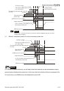
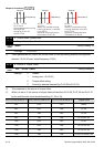
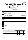
Negative feedback means: +target value – feedback. It is used for the detection value will be
increased by increasing the output frequency.
Positive feedback means: -target value + feedback. It is used for the detection value will be
decreased by increasing the output frequency.
08-01 Proportional Gain (P) Unit: 0.1
Control
mode
VF VFPG SVC FOCPG
Factory Setting: 80.0
Settings 0.0 to 500.0%
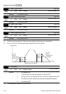
This parameter determinates the gain of the feedback loop. If the gain is large, the response
will be strong and immediate (if the gain is too large, vibration may occur). If the gain is small,
the response will weak and slow.
08-02 Integral Gain (I) Unit: 0.01
Control
mode
VF VFPG SVC FOCPG
Factory Setting: 1.00
Settings 0.00 to 100.00 sec
This parameter determines the speed of response for the PID feedback loop. If the integral
time is long, the response will be slow. If the integral time is short, the response will be quick.
Be careful not to set(I) too small, since a rapid response may cause oscillation in the PID loop.
If the integral time is set as 0.00, Pr.08-02 will be disabled.