


Chapter 2 Installation and Wiring|
Revision August 2008, 03VE, SW V2.04 2-15
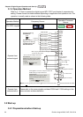
General
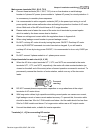
Keep control wiring as far as possible from the power wiring and in separate conduits to
avoid interference. If necessary let them cross only at 90º angle.
The AC motor drive control wiring should be properly installed and not touch any live
power wiring or terminals.
NOTE
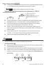
If a filter is required for reducing EMI (Electro Magnetic Interference), install it as close as
possible to AC drive. EMI can also be reduced by lowering the Carrier Frequency.
When using a GFCI (Ground Fault Circuit Interrupter), select a current sensor with
sensitivity of 200mA, and not less than 0.1-second detection time to avoid nuisance
tripping.
DANGER!
Damaged insulation of wiring may cause personal injury or damage to circuits/equipment if it comes
in contact with high voltage.
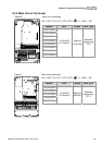
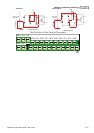
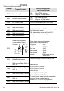
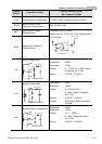
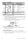
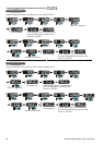
The specification for the control terminals
+10V
MO1 MO2
MI3
MI4
MI5
MI6
DFM
+24V
DCM
ACM
AVI
ACI
AFM
MCM
RA
RB
RC
MRC
MRA
REV
MI2
FWD
MI1
AUI
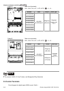
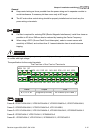
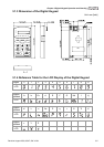
The Position of the Control Terminals
Frame Torque Wire
B, C, D, E, E1 8 kgf-cm (6.9 in-lbf) 22-14 AWG (0.3-2.1mm
2
)
NOTE
Frame B: VFD007V23A/43A-2, VFD015V23A/43A-2, VFD022V23A/43A-2, VFD037V23A/43A-2;
Frame C: VFD055V23A/43A-2, VFD075V23A/43A-2, VFD110V43B-2,
Frame D: VFD110V23A/43A-2, VFD150V23A/43A-2, VFD185V23A/43A-2, VFD220V23A/43A-2
Frame E: VFD300V43A-2, VFD370V43A-2, VFD450V43A-2
Frame E1: VFD300V23A-2, VFD370V23A-2, VFD550V43C-2, VFD750V43C-2