


Appendix B Accessories|
B-22 Revision August 2008, 03VE, SW V2.04
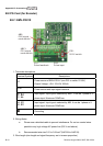
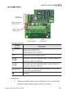
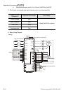
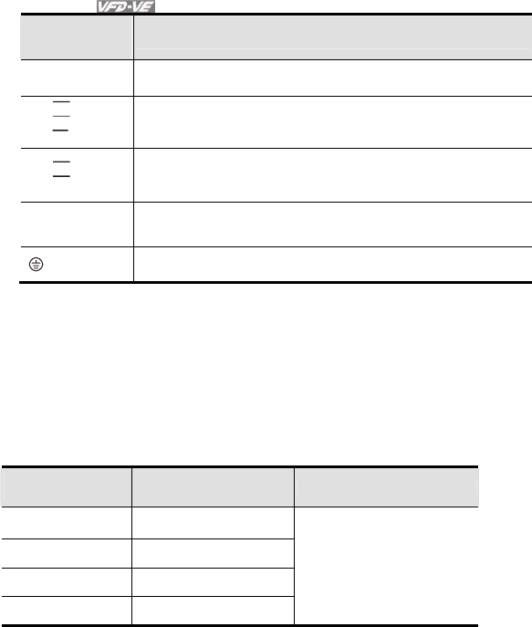
Terminal
Symbols
Descriptions
DCM
Power source and input signal common
A1,
B1,
Z1,
A1
B1
Z1
Input signal from encoder. Input type is selected by ABZ1. It can be
1-phase or 2-phase input. Maximum 300kP/sec
A2,
B2,
A2
B2
Input signal from encoder. Input type is selected by AB2. It can be 1-
phase or 2-phase input. Maximum 300kP/sec
A/O, B/O, Z/O
Output signal. It has division frequency function (Pr.10-16), open
collector: max. output DC20V 50mA
Grounding
2. Wiring Notes
a. Please use a shielded cable to prevent interference. Do not run control wires
parallel to any high voltage AC power line (200 V and above).
b. Recommended wire size 0.21 to 0.81mm
2
(AWG24 to AWG18).
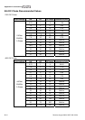
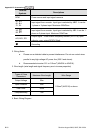
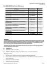
3. Wire length: (wire length and signal frequency are in inverse proportion)
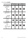
Types of Pulse
Generators
Maximum Wire Length Wire Gauge
Output Voltage 50m
Open Collector 50m
Line Driver 300m
Complementary 70m
1.25mm
2
(AWG16) or above
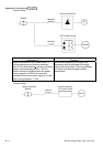
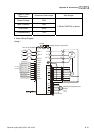
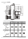
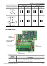
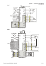
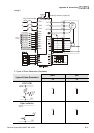
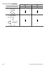
4. Basic Wiring Diagram