


Chapter 4 Parameters|
4-40 Revision August 2008, 03VE, SW V2.04
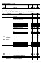
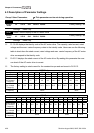
00-04 Content of Multi-Function function Display
Settings 0 Display the output current in A supplied to the motor
U
1
Display the counter value which counts the number of
pulses on TRG terminal
U
2 Display actual output frequency (H)
U
3
Display the actual DC BUS voltage in VDC of the AC
motor drive
U
4
Display the output voltage in VAC of terminals U, V, W
to the motor.
U
5
Display the power factor angle in º of terminals U, V, W
to the motor.
U
6
Display the output power in kW of terminals U, V and W
to the motor.
U
7
Display the actual motor speed in rpm (enabled when
using with PG card).
U
8
Display the estimated value of torque in Nm as it relates
to current.
U
9
Display PG position. When Pr.10-01 is set to 1 or 2, it
means that motor angle is 0~4XPr.10-00.
U
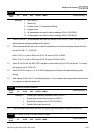
10 Display analog feedback signal value in %.
U
11
Display the signal of AVI analog input terminal in %.
Range 0~10V corresponds to 0~100%. (1.)
U
12
Display the signal of ACI analog input terminal in %.
Range 4~20mA/0~10V corresponds to 0~100%. (2.)
U
13
Display the signal of AUI analog input terminal in %.
Range -10V~10V corresponds to 0~100%. (3.)
U
14
Display the temperature of heat sink in °C.
U
15
Display the temperature of IGBT in °C.
U
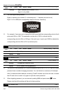
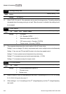
16 Display digital input status ON/OFF (i)
U
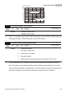
17 Display digital output status ON/OFF (o)
U
18 Display multi-step speed
U
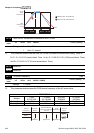
19 The corresponding CPU pin status of digital input (i.)
U
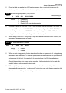
20 The corresponding CPU pin status of digital output (o.)
U