


Chapter 2 Installation and Wiring|
2-14 Revision August 2008, 03VE, SW V2.04
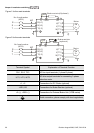
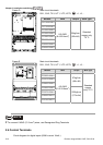
Terminal
Symbol
Terminal Function
Factory Settings (SINK)
ON: Connect to DCM
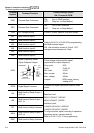
AFM
Analog output meter
A
FM
A
CM
0~20mA
Impedance: 18.5kΩ (voltage output)
1.1mΩ (current output)
Output current 20mA max
Resolution: max. frequency corresponds to
0-10V
Range: 0 ~ 10V/0 ~ 20mA
Function: Pr.03-18
Switch: AFM switch, factory setting is 0-
10V
ACM
Analog control signal
(common)
Common for AVI, ACI, AUI, AFM
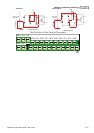
*Control signal wiring size: 18 AWG (0.75 mm
2
) with shielded wire.
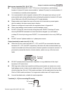
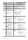
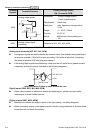
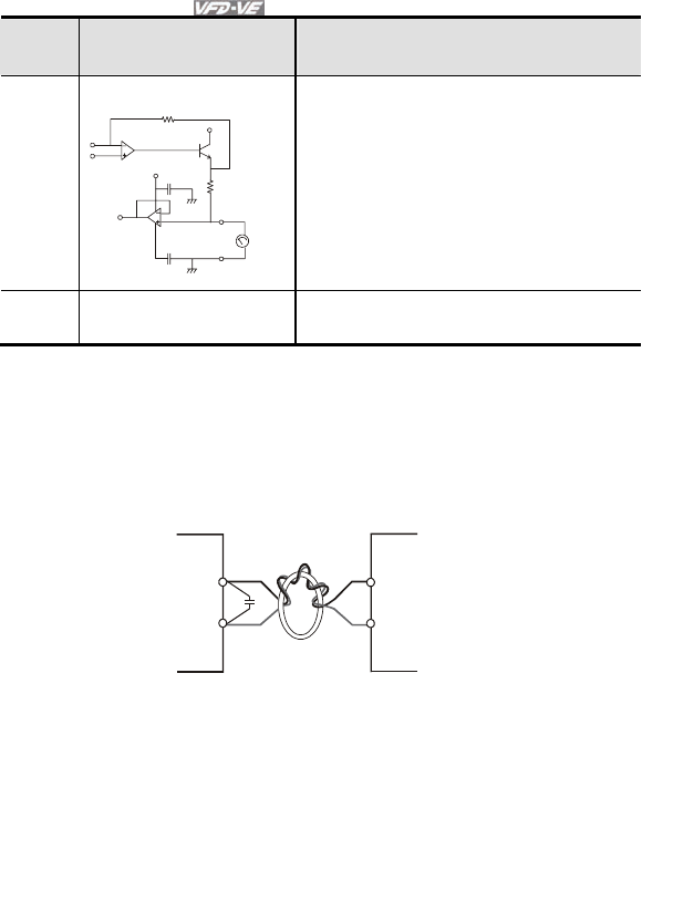
Analog input terminals (AVI, ACI, AUI, ACM)
Analog input signals are easily affected by external noise. Use shielded wiring and keep it
as short as possible (<20m) with proper grounding. If the noise is inductive, connecting
the shield to terminal ACM can bring improvement.
If the analog input signals are affected by noise from the AC motor drive, please connect
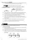
a capacitor and ferrite core as indicated in the following diagrams:
C
AVI/ACI/AUI
ACM
ferrite core
wind each wires 3 times or more around the core
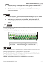
Digital inputs (FWD, REV, MI1~MI6, DCM)
When using contacts or switches to control the digital inputs, please use high quality
components to avoid contact bounce.
Digital outputs (MO1, MO2, MCM)
Make sure to connect the digital outputs to the right polarity, see wiring diagrams.
When connecting a relay to the digital outputs, connect a surge absorber or fly-back diode
across the coil and check the polarity.