


Chapter 4 Parameters|
Revision August 2008, 03VE, SW V2.04 4-41
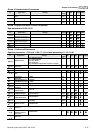
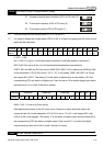
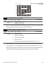
00-04 Content of Multi-Function function Display
21 Number of actual motor revolution (PG1 of PG card) (Z)
U
22 Pulse input frequency (PG2 of PG card) (4)
U
23 Pulse input position (PG2 of PG card) (4.)
U
This parameter sets the display when Pr. 00-03 is set to 2.
It is used to display the content when LED U is ON. It is helpful for getting the AC motor drive’s
status by this parameter.
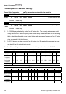
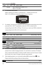
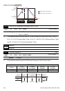
Terminal MI14 MI13 MI12 MI11 MI10 MI9 MI8 MI7 MI6 MI5 MI4 MI3 MI2 MI1 REV FWD
Status 0 0 0 0 000010 00011 0
0: OFF, 1: ON
MI1: Pr.02-01 is set to 1 (multi-step speed command 1/multi-step position command 1)
MI6: Pr.02-06 is set to 8 (the 1st, 2nd acceleration/deceleration time selection)
If REV, MI1 and MI6 are ON, the value is 0000 0000 1000 01102 in binary and 0086H in HEX.
At the meanwhile, if Pr.00-04 is set to “16” or “19”, it will display “0086” with LED U is ON on
the keypad KPV-CE01. The setting 16 is the status of digital input and the setting 19 is the
corresponding CPU pin status of digital input. User can set to 16 to monitor digital input status
and then set to 19 to check if the wire is normal.
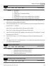
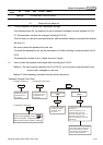
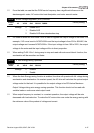
Terminal Reserved Reserved Reserved MO2 MO1 RA MRA
Status 0 0 0 0000010 0 00 1 1 0
MRA: Pr.02-11 is set to 9 (Drive ready).
After applying the power to the AC motor drive, if there is no other abnormal status, the
contact will be ON. At the meanwhile, if Pr.00-04 is set to 17 or 20, it will display 0001 with
LED U is ON on the keypad. The setting 17 is the status of digital output and the setting 20 is
the corresponding CPU pin status of digital output. User can set 17 to monitor the digital
output status and then set to 20 to check if the wire if normal.
00-05 User Defined Coefficient K