


Chapter 4 Parameters|
Revision August 2008, 03VE, SW V2.04 4-23
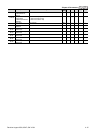
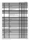
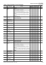
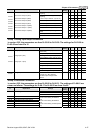
Group 10 Speed Feedback Control Parameters
Pr. Explanation Settings
Factory
Setting
VF VFPG
SVC
FOCPG
TQRPG
10-00 Encoder Pulse 1~20000 600
○
○ ○
10-01 Encoder Input Type
Setting
0: Disable
1: Phase A leads in a forward run command and phase
B leads in a reverse run command
2: Phase B leads in a forward run command and phase
A leads in a reverse run command
3: Phase A is a pulse input and phase B is a direction
input. (low input=reverse direction, high input=forward
direction)
4: Phase A is a pulse input and phase B is a direction
input. (low input=forward direction, high input=reverse
direction)
5: Single-phase input
0
○
○ ○
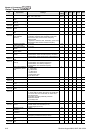
10-02
PG Feedback Fault
Treatment
0: Warn and keep operation
1: Warn and ramp to stop
2: Warn and coast to stop
2
○
○ ○
10-03
Detection Time for PG
Feedback Fault
0.00~10.0 sec 1.0
○
○ ○
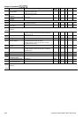
10-04
ASR (Auto Speed
Regulation) Control
( P) 1
0~40 10
○
○
10-05
ASR (Auto Speed
Regulation) Control (I)
1
0.000~10.000 sec 0.100
○
○
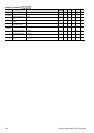
10-06
ASR (Auto Speed
Regulation) Control
( P) 2
0~40 10
○
○
10-07
ASR (Auto Speed
Regulation) Control (I)
2
0.000~10.000 sec 0.100
○
○
10-08
ASR 1/ASR2 Switch
Frequency
5.00~600.00Hz 7.00
○
○
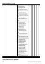
10-09
ASR Primary Low
Pass Filter Gain
0.000~0.350 sec 0.008
○
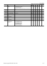
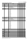
10-10
PG Stall Level 0~120% (0: disable) 115
○
○
10-11
PG Stall Detection
Time
0.0~2.0 sec 0.1
○
○
10-12
PG Slip Range 0~50% (0: disable) 50
○
○
10-13
PG Slip Detection
Time
0.0~10.0 sec 0.5
○
○
10-14
PG Stall and Slip Error
Treatment
0: Warn and keep operation
1: Warn and ramp to stop
2: Warn and coast to stop
2
○
○
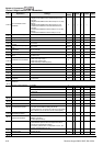
10-15
Pulse Input Type
Setting
0: Disable
1: Phase A leads in a forward run command and phase
B leads in a reverse run command
2: Phase B leads in a forward run command and phase
A leads in a reverse run command
3: Phase A is a pulse input and phase B is a direction
input. (low input=reverse direction, high input=forward
direction)
4: Phase A is a pulse input and phase B is a direction
input. (low input=forward direction, high input=reverse
direction)
0
○ ○ ○ ○ ○
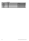
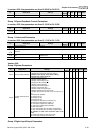
10-16
Output Setting for
Frequency Division
(denominator)
1~255 1
○
○ ○
10-17
PG Electrical Gear A
(Channel 1 of PG
card)
1~5000 100
○
○
10-18
PG Electrical Gear B
(Channel 2 of PG
card)
1~5000 100
○
○
10-19
PG Position Control
Point (Home)
0~20000 0
○
○
10-20
Range for PG Position
Attained (Home range)
0~20000 10
○
○