


Chapter 2 Installation and Wiring|
2-6 Revision August 2008, 03VE, SW V2.04
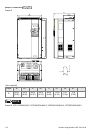
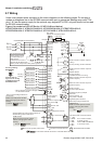
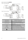
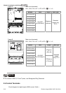
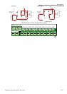
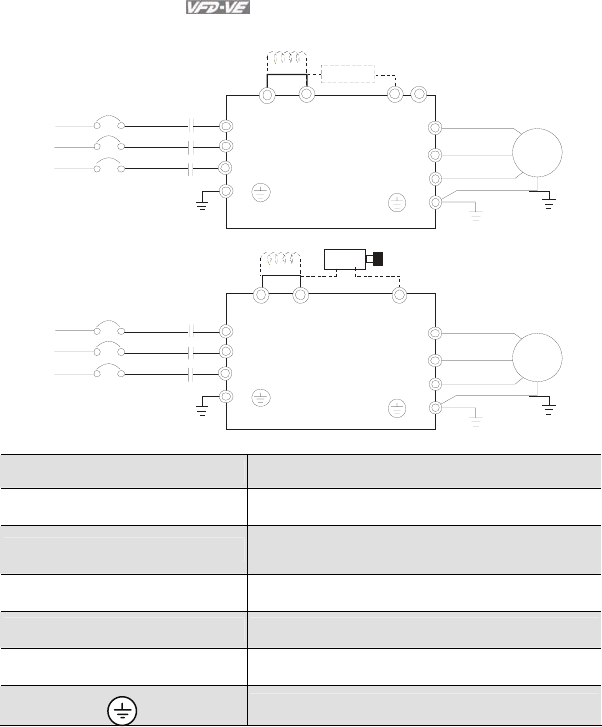
Figure 1 for the main terminals
R(L1)
S(L2)
T(L3)
R
S
T
U(T1)
V(T2)
W(T3)
IM
3~
MC
E
E
+1 +2/B1
B2
No-fuse breaker
(NFB)
Brak e res istor(O ptional)
Motor
-
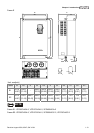
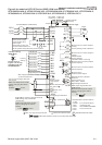
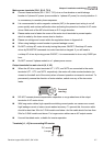
Figure 2 for the main terminals
R(L1)
S(L2)
T(L3)
R
S
T
U(T1)
V(T2)
W(T3)
IM
3~
MC
E
E
VFDB
+1
+2
-
No-fuse breaker
(NFB)
Brak e resistor
(optional)
Motor
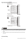
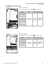
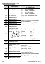
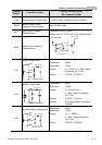
Terminal Symbol Explanation of Terminal Function
R/L1, S/L2, T/L3 AC line input terminals (1-phase/3-phase)
U/T1, V/T2, W/T3
AC drive output terminals for connecting 3-phase
induction motor
+1, +2 Connections for DC Choke (optional)
+2/B1, B2 Connections for Brake Resistor (optional)
+2~(-), +2/B1~(-) Connections for External Brake Unit (VFDB series)
Earth connection, please comply with local regulations.