


Chapter 4 Parameters|
Revision August 2008, 03VE, SW V2.04 4-7
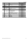
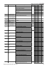
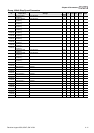
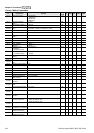
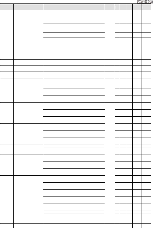
Pr. Explanation Settings
Factory
Setting
VF
VFPG
SVC
FOCPG
TQRPG
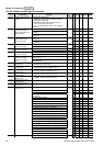
44: Reset initial reel diameter
○ ○ ○ ○ ○
45: Reset initial reel diameter 0
○ ○ ○ ○ ○
46: Reset initial reel diameter 1
○ ○ ○ ○ ○
47: Reset PID control integration of tension
○ ○ ○ ○ ○
48: Mechanical gear ratio switch
○ ○ ○
49: Reserved
50: Reserved
02-07
UP/DOWN Key Mode
0: up/down by the accel/decel time
1: up/down constant speed (Pr.02-08)
0
○ ○ ○ ○
02-08
The
A
cceleration/Deceleration
Speed of the UP/DOWN
Key with Constant Speed
0.01 ~ 1.00Hz/ms 0.01
○ ○ ○ ○
02-09
Digital Input Response
Time
0.001~ 30.000 sec 0.005
○ ○ ○ ○ ○
02-10
Digital Input Operation
Direction
0 ~ 65535 0
○ ○ ○ ○ ○
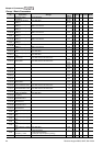
0: No function
11
○ ○ ○ ○ ○
02-11
Multi-function Output 1
RA, RB, RC(Relay1)
1: Operation indication
○ ○ ○ ○ ○
2: Operation speed attained 1
○ ○ ○ ○ ○
02-12
Multi-function Output 2
MRA, MRC (Relay2)
3: Desired frequency attained 1 (Pr.02-19)
○ ○ ○ ○ ○
4: Desired frequency attained 2 (Pr.02-21) 0
○ ○ ○ ○
5: Zero speed (frequency command)
○ ○ ○ ○
02-13
Multi-function Output 3
(MO1)
6: Zero speed with stop (frequency command)
○ ○ ○ ○
7: Over torque (OT1) (Pr.06-06~06-08)
○ ○ ○ ○ ○
8: Over torque (OT2) (Pr.06-09~06-11)
○ ○ ○ ○ ○
9: Drive ready 0
○ ○ ○ ○ ○
02-14
Multi-function Output 4
(MO2)
10: User-defined Low-voltage Detection
○ ○ ○ ○ ○
11: Malfunction indication
○ ○ ○ ○ ○
12: Mechanical brake release (Pr.02-31)
○ ○ ○ ○ ○
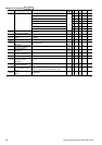
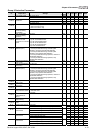
02-35
Multi-function Output 5
(MO3)
13: Overheat
○ ○ ○ ○ ○
14: Software brake signal
○ ○ ○ ○ ○
15: PID feedback error
○ ○ ○ ○ ○
02-36
Multi-function Output 6
(MO4)
16: Slip error (oSL)
○ ○ ○ ○
17: Terminal count value attained (Pr.02-16)
○ ○ ○ ○ ○
18: Preliminary count value attained (Pr.02-17)
○ ○ ○ ○ ○
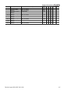
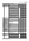
02-37
Multi-function Output 7
(MO5)
19: Baseblock (B.B.) Indication
○ ○ ○ ○ ○
20: Warning output
○ ○ ○ ○ ○
21: Over voltage warning
○ ○ ○ ○ ○
02-38
Multi-function Output 8
(MO6)
22: Over-current stall prevention warning
○ ○ ○ ○ ○
23: Over-voltage stall prevention warning
○ ○ ○
24: Operation mode indication
○ ○ ○ ○ ○
02-39
Multi-function Output 9
(MO7)
25: Forward command
○ ○ ○ ○
26: Reverse command
○ ○ ○ ○
27: Output when current >= Pr.02-32
○ ○ ○ ○ ○
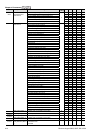
02-40
Multi-function Output 10
(MO8)
28: Output when current < Pr.02-32
○ ○ ○ ○ ○
29: Output when frequency >= Pr.02-33
○ ○ ○ ○ ○
30: Output when frequency < Pr.02-33
○ ○ ○ ○ ○
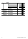
02-41
Multi-function Output 11
(MO9)
31: Y-connection for the motor coil
○ ○ ○ ○
32: Δ connection for the motor coil
○ ○ ○ ○
33: Zero speed (actual output frequency)
○ ○ ○ ○
02-42
Multi-function Output 12
(MOA)
34: Zero speed with Stop (actual output frequency)
○ ○ ○ ○
35: Error output selection 1 (Pr.06-23)
○ ○ ○ ○ ○
36: Error output selection 2 (Pr.06-24)
○ ○ ○ ○ ○
37: Error output selection 3 (Pr.06-25)
○ ○ ○ ○ ○
38: Error output selection 4 (Pr.06-26)
○ ○ ○ ○ ○
39: Position attained (Pr.10-19)
○
40: Speed attained (including zero speed)
○ ○ ○ ○
41: Multi-position attained
○
42: Crane function
○ ○ ○ ○
43: Motor zero-speed output (Pr.02-43)
○ ○ ○ ○