


Chapter 4 Parameters|
4-148 Revision August 2008, 03VE, SW V2.04
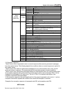
2 Modbus ASCII mode, protocol <7,E,1>
3 Modbus ASCII mode, protocol <7,O,1>
4 Modbus ASCII mode, protocol <7,E,2>
5 Modbus ASCII mode, protocol <7,O,2>
6 Modbus ASCII mode, protocol <8,N,1>
7 Modbus ASCII mode, protocol <8,N,2>
8 Modbus ASCII mode, protocol <8,E,1>
9 Modbus ASCII mode, protocol <8,O,1>
10 Modbus ASCII mode, protocol <8,E,2>
11 Modbus ASCII mode, protocol <8,O,2>
12 Modbus RTU mode, protocol <8,N,1>
13 Modbus RTU mode, protocol <8,N,2>
14 Modbus RTU mode, protocol <8,E,1>
15 Modbus RTU mode, protocol <8,O,1>
16 Modbus RTU mode, protocol <8,E,2>
17 Modbus RTU mode, protocol <8,O,2>
09-09 Response Delay Time Unit: 0.1
Control
mode
VF VFPG SVC FOCPG TQRPG
Factory Setting: 2.0
Settings 0.0 ~ 200.0 msec
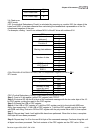
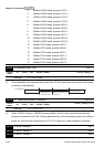
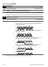
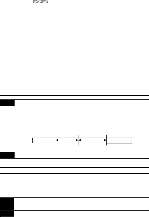
This parameter is the response delay time after AC drive receives communication command
as shown in the following.
PC or PLC command
Handling time
of the AC drive
Response Delay Time
Pr.09-09
Response Message
of the AC Drive
RS-485 BUS
09-10 Transmission Master Frequency Unit: 0.01
Control
mode
VF VFPG SVC FOCPG TQRPG
Factory Setting: 60.00
Settings 0.00 ~ 600.00 Hz
When Pr.00-20 is set to 1 (RS485 communication). The AC motor drive will save the last
frequency command into Pr.09-10 when abnormal turn-off or momentary power loss. After re-
power on, it will with the frequency set in Pr.09-10 if there is no new frequency command.
09-11 Block Transfer 1 Unit: 1
09-12 Block Transfer 2 Unit: 1
09-13 Block Transfer 3 Unit: 1