


Chapter 3 Digital Keypad Operation and Start Up|
3-6 Revision August 2008, 03VE, SW V2.04
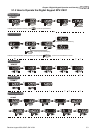
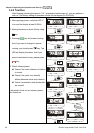
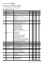
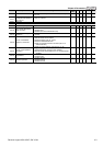
3.1.5 Operation Method
Refer to 3.1.2 How to operate the digital keypad KPV-CE01 and chapter 4 parameters for
setting. Please choose a suitable method depending on application and operation rule. The
operation is usually used as shown in the following table.
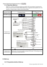
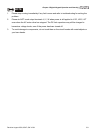
3.2 Start-up
3.2.1 Preparations before Start-up
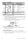
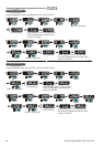
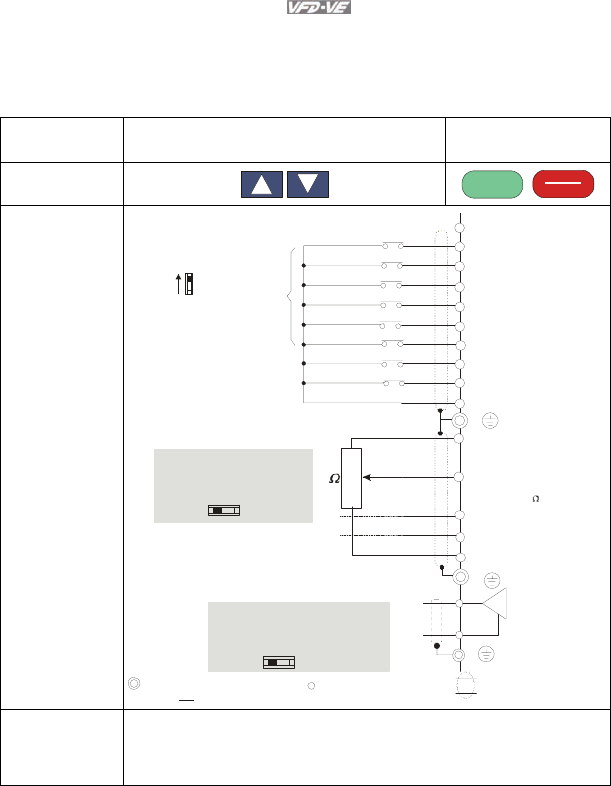
Operation Method Frequency Source
Operation Command
Source
KPV-CE01 keypad
RUN
RESET
STOP
Operate from
external signal
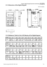
Sw1
Sink
Source
Factory setting:
SINK Mode
Please refer to
Figure 3 for wiring
of SINK mode and
SOURCEmode.
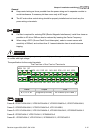
AVI
ACI
AUI
ACM
+10V
5K
3
2
1
Power supply
+10V 20mA
Master Frequency
0 to 10V 47k
Analog Signal Common
E
MI1
MI2
MI3
MI4
MI6
MI5
DCM
+24V
FWD/STOP
REV/STOP
Multi-step 1
Multi-step 2
Multi-step 3
Multi-step 4
No function
Digital Signal Common
Factory
setting
* Don't apply the mains voltage directly
to above terminals.
E
No function
REV
FWD
ACI current/voltage selection
AFM
ACM
Analog Signal common
E
4~20mA/0~10V
-10~+10V
0-20mA
0-10V
ACI Switch
Make sure that power is OFF
before changing the switch
setting.
0~10VDC/2mA
AFM analog output selection
Analog Multi-function Output Terminal
0-10V
0-20mA
AFM Switch
Make sure that power is OFF
before changing the switch
setting.
Control circuit terminals
Shielded leads & Cable
Main circuit (power) terminals
Operate from
communication
Please refer to the communication address 2000H and 2119H settings in the
communication address definition.