


Chapter 4 Parameters|
Revision August 2008, 03VE, SW V2.04 4-107
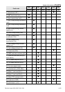
Group 7 Special Parameters
07-00 Software Brake Level Unit: 0.1
Control
mode
VF VFPG SVC FOCPG TQRPG
Settings 230V series 350.0~450.0Vdc Factory Setting: 380.0
460V series 700.0~900.0Vdc Factory Setting: 760.0
This parameter sets the DC-bus voltage at which the brake chopper is activated.
07-01 DC Brake Current Level Unit: 1
Control
mode
VF VFPG SVC FOCPG TQRPG
Factory Setting: 0
Settings 0 to 100%
This parameter sets the level of DC Brake Current output to the motor during start-up and
stopping. When setting DC Brake Current, the Rated Current (Pr.00-01) is regarded as 100%.
It is recommended to start with a low DC Brake Current Level and then increase until proper
holding torque has been attained.
When it is in FOCPG/TQRPG mode, it can enable DC brake function by setting to any value.
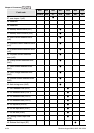
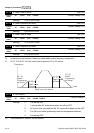
07-02 DC Brake Time during Start-up Unit: 0.1
Control
mode
VF VFPG SVC FOCPG TQRPG
Factory Setting: 0.0
Settings 0.0 to 60.0 sec
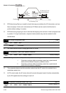
This parameter determines the duration of the DC Brake current after a RUN command. When
the time has elapsed, the AC motor drive will start accelerating from the Minimum Frequency
(Pr.01-05).
07-03 DC Brake Time during Stopping Unit: 0.01
Control
mode
VF VFPG SVC FOCPG TQRPG
Factory Setting: 0.00
Settings 0.00 to 60.00 sec
This parameter determines the duration of the DC Brake current during stopping.
07-04 Start-Point for DC Brake Unit: 0.01
Control
mode
VF VFPG SVC TQRPG
Factory Setting: 0.00
Settings 0.00 to 600.00Hz
This parameter determines the frequency when DC Brake will begin during deceleration.