


Chapter 4 Parameters|
Revision August 2008, 03VE, SW V2.04 4-153
Settings 0 to 50% (0: disable)
10-13 PG Slip Detection Time Unit: 0.1
Control
mode
VFPG FOCPG
Factory Setting: 0.5
Settings 0.0 to 10.0 sec
10-14
PG Stall and Slip Error Treatment
Control
mode
VFPG FOCPG
Factory Setting: 2
Settings 0 Warn and keep operating
1 Warn and RAMP to stop
2 Warn and COAST to stop
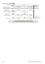
When the value of (rotation speed – motor frequency) exceeds Pr.10-12 setting, detection time
exceeds Pr.10-13 or motor frequency exceeds Pr.10-10 setting, it will start to accumulate time.
If detection time exceeds Pr.10-11, the PG feedback signal error will occur. Refer to Pr.10-14
PG stall and slip error treatment.
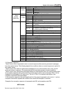
10-15
Pulse Input Type Setting
Control
mode
VF VFPG SVC FOCPG TQRPG
Factory Setting: 0
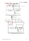
Settings 0 Disable
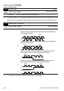
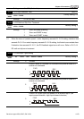
1
Phase A leads in a forward run command and phase B leads in a
reverse run command
A
B
FWD
REV
2
Phase B leads in a forward run command and phase A leads in a
reverse run command
A
B
FWD
REV
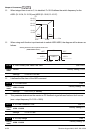
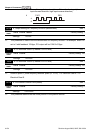
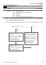
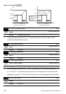
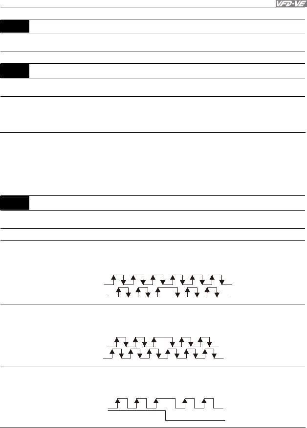
3
Phase A is a pulse input and phase B is a direction input. (low
input=reverse direction, high input=forward direction)
A
B
FWD
REV