


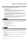
Chapter 2 Installation and Wiring|
2-2 Revision August 2008, 03VE, SW V2.04
2.1 Wiring
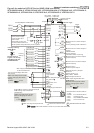
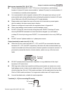
Users must connect wires according to the circuit diagrams on the following pages. Do not plug a
modem or telephone line to the RS-485 communication port or permanent damage may result. The
pins 1 & 2 are the power supply for the optional copy keypad KPV-CE01 only and should not be used
for RS-485 communication.
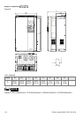
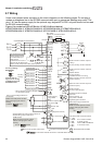
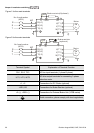
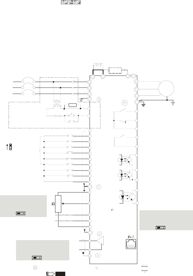
Figure 1 for models of VFD-VE Series (15 HP/11kW and below)
VFD007V23A/43A-2, VFD015V23A/43A-2, VFD022V23A/43A-2, VFD037V23A/43A-2,
VFD055V23A/43A-2, VFD075V23A/43A-2, VFD110V43B-2, VFD110V23A/43A-2
+2/B1
B2
Brake resistor
(optional)
+1
Jumper
DC choke
(optional)
Main circuit (power) terminals
Control circuit terminals
Shielded leads & Cable
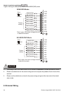
Sw1
Sink
Source
Factory setting:
SINK Mode
Please refer to
Figure 3 for wiring
of SINK mode and
SOURCEmode.
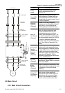
R(L1)
S(L2)
T(L3)
Fuse/NFB(No Fuse Breaker)
SA
OFF
ON
MC
MC
RB
RC
Recommended Circuit
when power supply
is turned OFF by a
fault output.
R(L1)
S(L2)
T(L3)
E
AVI
ACI
AUI
ACM
+10V
5K
3
2
1
Power supply
+10V 20mA
Master Frequency
0 to 10V 47k
Analog Signal Common
E
U(T1)
V(T2)
W(T3)
IM
3~
RA
RB
RC
Motor
RS-485 serial communication
1: +EV
2: GND
3: SG-
4: SG+
5: NC
6: NC
E
DFM
DCM
Digital Frequency Output
Ter min al
factory setting: 1:1
Duty=50%, 10VDC
Digital Signal Common
Multi-function contact output 1
(relay)
factory setting: fault indication
MO1
MO2
MCM
Multi-function contact output 3
(photocoupler)
Multi-function
Photocoupler Output
Multi-function contact output 4
(photocoupler)
MRA
MRC
Multi-function contact output 2
(relay)
48VDC 50mA
factory setting:
indicates that it is running
DFM output signal selection
MI1
MI2
MI3
MI4
MI6
MI5
DCM
+24V
FWD/STOP
REV/STOP
Multi-step 1
Multi-step 2
Multi-step 3
Multi-step 4
No function
Digital Signal Common
Factory
setting
* Don't apply the mains voltage directly
to above terminals.
E
No function
REV
FWD
ACI current/voltage selection
AFM
ACM
Analog Signal common
E
The brake resistor is built-in to model VFD110V43B.
NOTE
If the fault occurs, the
contact will be ON to turn
off the power and protect the power system.
-
OC
TP
DFM Switch
Make sure that power is OFF
before changing the switch
setting.
4~20mA/0~10V
-10~+10V
0-20mA
0-10V
ACI Switch
Make sure that power is OFF
before changing the switch
setting.
0~10VDC/2mA
AFM analog output selection
Analog Multi-function Output Terminal
0-10V
0-20mA
AFM Switch
Make sure that power is OFF
before changing the switch
setting.
For communication,
it needs to use
VFD-USB01/IFD8500
to connect to PC.