


Chapter 4 Parameters|
4-108 Revision August 2008, 03VE, SW V2.04
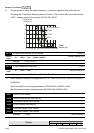
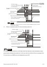
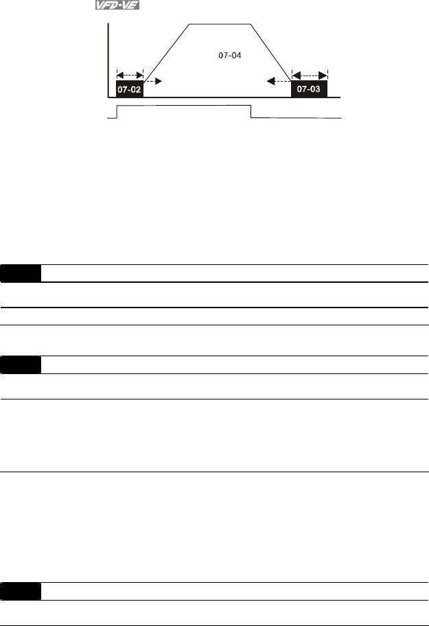
ON
OFF
01-09
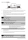
Output frequency
Run/Stop
Time
DC Braking Time
DC Braking Time
during Stopping
Minimum
output
frequency
Start-point for
DC braking
time during
stopping
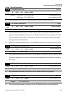
DC Brake during Start-up is used for loads that may move before the AC drive starts, such as
fans and pumps. Under such circumstances, DC Brake can be used to hold the load in
position before setting it in motion.
DC Brake during stopping is used to shorten the stopping time and also to hold a stopped load
in position. For high inertia loads, a dynamic brake resistor may also be needed for fast
decelerations.
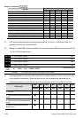
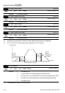
07-05 DC Brake Proportional Gain Unit: 1
Control
mode
VF VFPG SVC
Factory Setting: 50
Settings 1 to 500Hz
It is used to set the output voltage gain when DC brake.
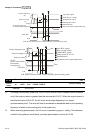
07-06 Momentary Power Loss Operation Selection
Control
mode
VF VFPG SVC FOCPG TQRPG
Factory Setting: 0
Settings 0 Operation stops after momentary power loss.
1 Operation continues after momentary power loss, speed search
starts with the Master Frequency reference value.
2 Operation continues after momentary power loss, speed search
starts with the minimum frequency.
This parameter determines the operation mode when the AC motor drive restarts from a
momentary power loss.
In PG control mode, the AC motor drive will execute the speed search function automatically
by the PG speed when this setting isn’t set to 0.
07-07 Maximum Allowable Power Loss Time Unit: 0.1
Control
mode
VF VFPG SVC FOCPG TQRPG
Factory Setting: 2.0