


Chapter 2 Installation and Wiring|
2-8 Revision August 2008, 03VE, SW V2.04
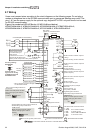
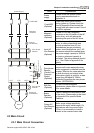
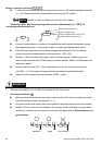
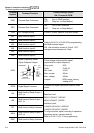
To improve power factor and reduce harmonics connect a DC reactor between terminals
[+1, +2]. Please remove the jumper before connecting the DC reactor.
NOTE
Models of 15kW and above have a built-in DC reactor.
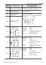
Terminals [+2/B1, B2] for connecting brake resistor and terminals [+1, +2/B1] for
connecting external brake unit
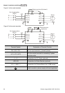
Brake unit(optional)
Refer to Appendix B for the use of
special braking resistor/unit
+2/B
1
B2
BR
+2/B
1
-
VFDB
BR
Brake resistor(optional
)
Connect a brake resistor or brake unit in applications with frequent deceleration ramps,
short deceleration time, too low brake torque or requiring increased brake torque.
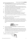
If the AC motor drive has a built-in brake chopper (all models of 11kW and below),
connect the external brake resistor to the terminals [
+
2/B1, B2].
Models of 15kW and above don’t have a built-in brake chopper. Please connect an
external optional brake unit (VFDB-series) and brake resistor. Refer to VFDB series user
manual for details.
Connect the terminals [+(P), -(N)] of the brake unit to the AC motor drive terminals
[+2(+2/B1), (-)]. The length of wiring should be less than 5m with twisted cable.
When not used, please leave the terminals [+2/B1, -] open.
WARNING!
1. Short-circuiting [B2] or [-] to [+2/B1] can damage the AC motor drive.
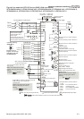
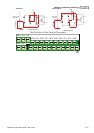
Grounding terminals (
)
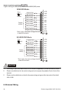
Make sure that the leads are connected correctly and the AC drive is properly grounded.
(Ground resistance should not exceed 0.1
Ω
.)
Use ground leads that comply with local regulations and keep them as short as possible.
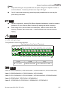
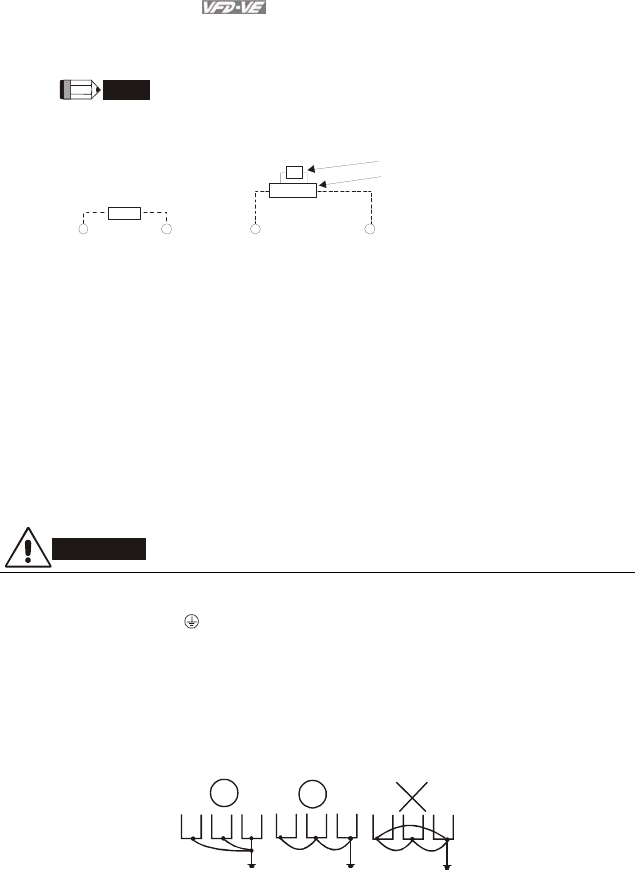
Multiple VFD-VE units can be installed in one location. All the units should be grounded
directly to a common ground terminal, as shown in the figure below. Ensure there are no
ground loops.
goodexcellent
not allowed