


Chapter 4 Parameters|
4-152 Revision August 2008, 03VE, SW V2.04
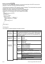
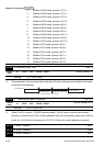
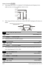
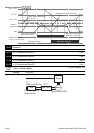
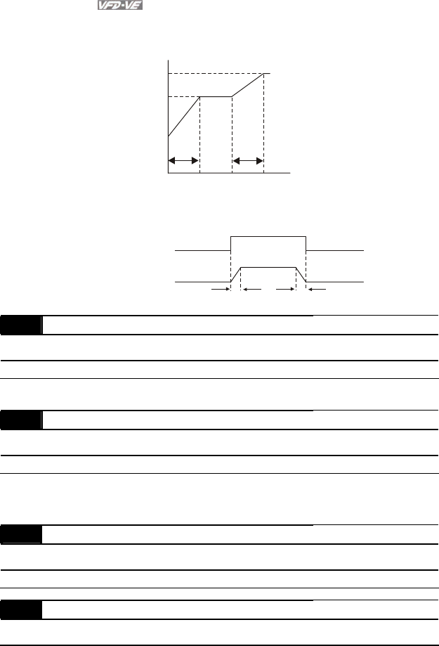
When integral time is set to 0, it is disabled. Pr.10-08 defines the switch frequency for the
ASR1 (Pr.10-04, Pr.10-05) and ASR2 (Pr.10-06, Pr.10-07).
10-08
10-04
10-05
10-06
10-07
Hz
PI
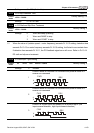
10-21
10-22
0H
z
5Hz
5Hz
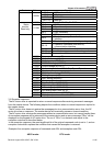
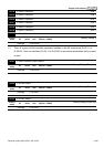
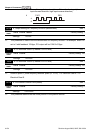
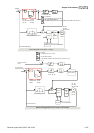
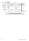
When using multi-function input terminals to switch ASR1/ASR2, the diagram will be shown as
follows.
ON
OFF
ASR 1
0.1 sec
OFF
0.1 sec
ASR 1
ASR 2
Setting multi-function input terminal to 27
(ASR1/ASR2 switch)
10-09 ASR Primary Low Pass Filter Gain Unit: 0.001
Control
mode
FOCPG
Factory Setting: 0.008
Settings 0.000 to 0.350 sec
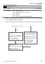
It defines the filter time of the ASR command.
10-10 PG Stall Level Unit: 1
Control
mode
VFPG FOCPG
Factory Setting: 115
Settings 0 to 120% (0: disable)
This parameter determines the maximum PG feedback signal allowed before a fault occurs.
(max. output frequency Pr.01-00 =100%)
10-11 PG Stall Detection Time Unit: 0.1
Control
mode
VFPG FOCPG
Factory Setting: 0.1
Settings 0.0 to 2.0 sec
10-12 PG Slip Range Unit: 1
Control
mode
VFPG FOCPG
Factory Setting: 50