


Chapter 2 Installation and Wiring|
2-4 Revision August 2008, 03VE, SW V2.04
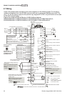
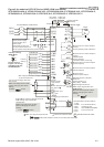
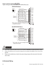
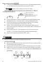
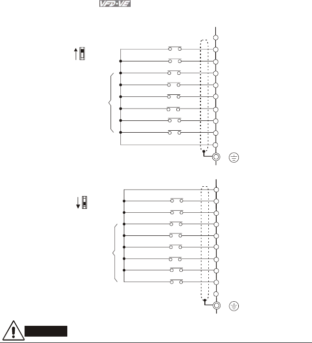
Figure 3 Wiring for SINK(NPN) mode and SOURCE(PNP) mode
*Don't apply the mains voltage directly
to above terminals.
FWD/STOP
REV/STOP
Multi-step1
Multi-step2
Multi-step3
Multi-step4
+24V
MI1
MI2
MI3
MI4
MI5
MI6
Factory
setting
SINK/NPN Mode
FWD
REV
No Function
No Function
Digital Signal Common
DCM
Sink
Source
SW1
E
*Don't apply the mains voltage directly
to above terminals.
FWD/STOP
REV/STOP
Multi-step1
Multi-step2
Multi-step3
Multi-step4
+24V
MI1
MI2
MI3
MI4
MI5
MI6
Factory
setting
SOURCE/PNP Mode
FWD
REV
No Function
No Function
DCM
E
Sink
Source
SW1
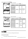
CAUTION!
1. The wiring of main circuit and control circuit should be separated to prevent erroneous actions.
2. Please use shield wire for the control wiring and not to expose the peeled-off net in front of the
terminal.
3. Please use the shield wire or tube for the power wiring and ground the two ends of the shield
wire or tube.
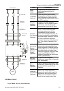
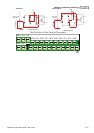
2.2 External Wiring