


Chapter 4 Parameters|
Revision August 2008, 03VE, SW V2.04 4-59
Group 2 Digital Input/Output Parameters
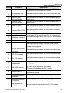
02-00 2-wire/3-wire Operation Control
Control
mode
VF VFPG SVC FOCPG TQRPG
Factory setting: 0
Settings 0 FWD/STOP, REV/STOP
1 FWD/STOP, REV/STOP (Line Start Lockout)
2 RUN/STOP, REV/FWD
3 RUN/STOP, REV/FWD (Line Start Lockout)
4 3-wire (momentary push button)
5 3-wire (momentary push button and Line Start Lockout)
Three of the six methods include a “Line Start Lockout” feature. When line start lockout is
enabled, the drive will not run once applying the power. The Line Start Lockout feature doesn’t
guarantee the motor will never start under this condition. It is possible the motor may be set in
motion by a malfunctioning switch.
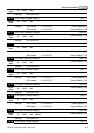
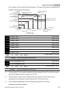
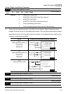
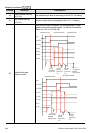
02-00 Control Circuits of the External Terminal
0, 1
2-wire operation control (1)
FWD/STOP
REV/STOP
FWD:("OPEN":STOP)
("CLOSE":FWD)
REV:("OPEN": STOP)
("CLOSE": REV)
V
FD-VE
DCM
FWD/STOP
REV/STOP
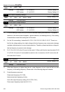
2, 3
2-wire operation control (2)
RUN/STOP
REV/FWD
FWD:("OPEN":STOP)
("CLOSE":RUN)
REV:("OPEN": FWD)
("CLOSE": REV)
V
FD-VE
DCM
RUN/STOP
FWD/REV
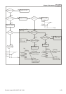
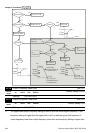
4, 5
3-wire operation control
FWD "CLOSE":RUN
MI1 "OPEN":STOP
REV/FWD "OPEN": FWD
"CLOSE": REV
V
FD-VE
DCM
STOP
REV/FWD
RUN
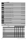
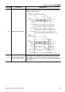
02-01 Multi-Function Input Command 1 (MI1)
Factory Setting: 1
02-02 Multi-Function Input Command 2 (MI2)
Factory Setting: 2
02-03 Multi-Function Input Command 3 (MI3)
Factory Setting: 3