


Appendix B Accessories|
B-18 Revision August 2008, 03VE, SW V2.04
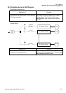
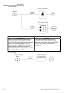
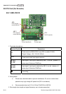
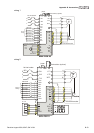
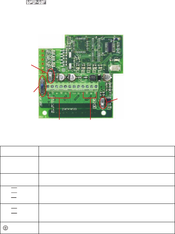
B.8 PG Card (for Encoder)
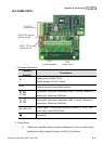
B.8.1 EMV-PG01X
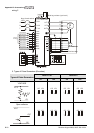
AB2:
PG2 signal
mode switch
ABZ1:
PG1 signal
mode switch
PG1
Pulse feedback
PG2
Pulse input
PS1:
5/12V switch
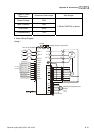
1. Terminals descriptions
Terminal Symbols Descriptions
VP
Power source of EMV-PG01X (use PS1 to switch 12V/5V)
Output Voltage: +5V/+12V±5% 200mA
DCM
Power source and input signal common
A1,
B1,
Z1,
A1
B1
Z1
Input signal. Input type is selected by ABZ1. It can be 1-phase or 2-
phase input. Maximum 300kP/sec
A2,
B2,
A2
B2
Input signal. Input type is selected by AB2. It can be 1-phase or 2-
phase input. Maximum 300kP/sec
Grounding
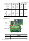
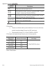
2. Wiring Notes
a. Please use a shielded cable to prevent interference. Do not run control wires
parallel to any high voltage AC power line (200 V and above).
b. Recommended wire size 0.21 to 0.81mm
2
(AWG24 to AWG18).
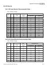
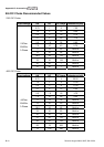
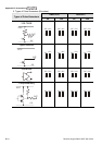
3. Wire length (wire length and signal frequency are in inverse proportion)