


Chapter 4 Parameters|
4-70 Revision August 2008, 03VE, SW V2.04
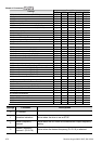
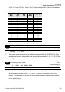
Control Mode
Settings
VF VFPG SVC FOCPG TQRPG
12: Mechanical brake release (Pr.02-31)
○ ○ ○ ○ ○
13: Overheat
○ ○ ○ ○ ○
14: Software brake signal
○ ○ ○ ○ ○
15: PID feedback error
○ ○ ○ ○ ○
16: Slip error (oSL)
○ ○ ○ ○
17: Terminal count value attained (Pr.02-16)
○ ○ ○ ○ ○
18: Preliminary count value attained (Pr.02-17)
○ ○ ○ ○ ○
19: Baseblock (B.B.) Indication
○ ○ ○ ○ ○
20: Warning output
○ ○ ○ ○ ○
21: Over voltage warning
○ ○ ○ ○ ○
22: Over-current stall prevention warning
○ ○ ○
23: Over-voltage stall prevention warning
○ ○ ○ ○ ○
24: Operation mode indication
○ ○ ○ ○ ○
25: Forward command
○ ○ ○ ○ ○
26: Reverse command
○ ○ ○ ○ ○
27: Output when current >= Pr.02-32
○ ○ ○ ○ ○
28: Output when current < Pr.02-32
○ ○ ○ ○ ○
29: Output when frequency >= Pr.02-33
○ ○ ○ ○ ○
30: Output when frequency < Pr.02-33
○ ○ ○ ○ ○
31: Y-connection for the motor coil
○ ○ ○ ○
32: Δ connection for the motor coil
○ ○ ○ ○
33: Zero speed (actual output frequency)
○ ○ ○ ○
34: Zero speed with Stop (actual output frequency)
○ ○ ○ ○
35: Error output selection 1 (Pr.06-23)
○ ○ ○ ○ ○
36: Error output selection 2 (Pr.06-24)
○ ○ ○ ○ ○
37: Error output selection 3 (Pr.06-25)
○ ○ ○ ○ ○
38: Error output selection 4 (Pr.06-26)
○ ○ ○ ○ ○
39: Position attained (Pr.10-19)
○
40: Speed attained (including zero speed)
○ ○ ○ ○
41: Multi-position attained
○
42: Crane function
○ ○ ○ ○
43: Motor zero-speed output (Pr.02-43)
○ ○ ○ ○
44: Max. reel diameter attained
○ ○ ○ ○ ○
45: Empty reel diameter attained
○ ○ ○ ○ ○
46: Broken belt detection
○ ○ ○ ○ ○
47: Break release at stop
○ ○ ○ ○ ○
48: Error PID feedback of tension
○ ○ ○ ○ ○
49: Reserved
50: Reserved
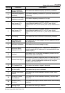
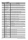
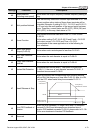
Settings Functions Descriptions
0 No Function
1 Operation Indication Active when the drive is not at STOP.
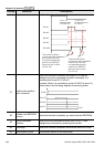
2
Master Frequency
Attained
Active when the AC motor drive reaches the output frequency
setting.
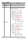
3
Desired Frequency
Attained 1 (Pr.02-19)
Active when the desired frequency (Pr.02-19) is attained.