


Chapter 4 Parameters|
Revision August 2008, 03VE, SW V2.04 4-67
Settings Functions Descriptions
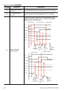
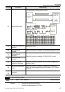
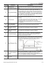
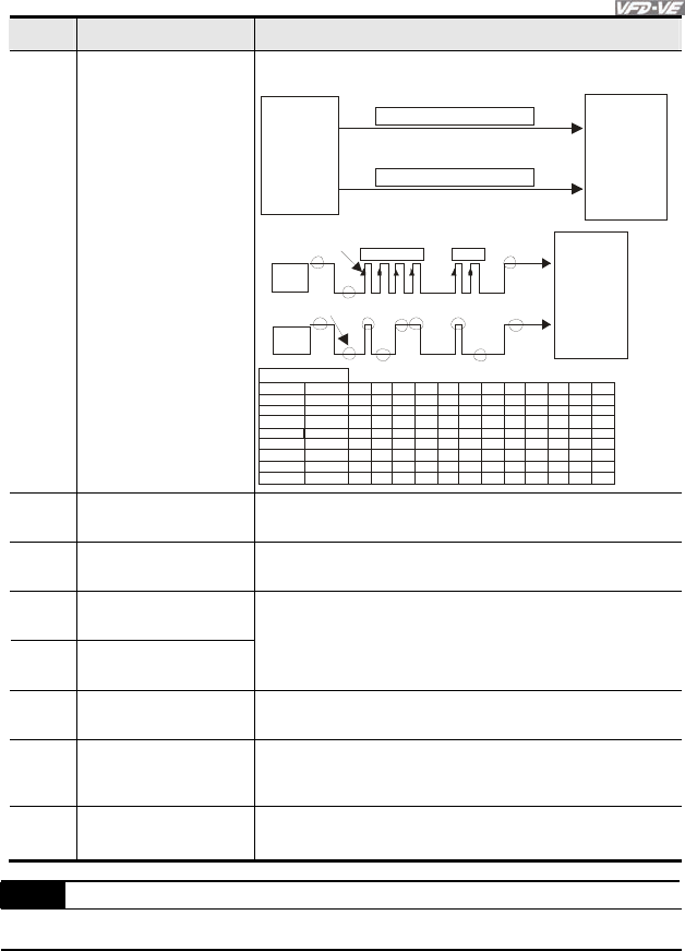
42 Serial position input
When using setting 41 and setting 42, it needs to use with 2
input terminals for multi-position control.
CNC
DO
SPI Positi on Command Clock
DI
DO
SPI Positi on Command Data
DI
Con troller
(PLC)
main
shaft
VFD-VE
PG position
control point
Pr.10-19
OSS
Clock
OSS
Data
1 2 3 4 11 12
b0
b11
Encoder b1b2b3b4b5b6b7b8b9
b10
360
180
90
45
137
308
40 96
40 95
20 48
10 24
51 2
15 58
35 04
36 87
0
1
00
0
00000000
11
1
1
1
1
1
1
1
1
1
00
0
000000001
0
0
00000000
1
0
00000000
1
0
00010110
1
1
0
0
0
0
0
1
1011000011
1
0
0110011111
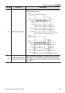
PG position
co ntr ol point
Pr.10-19
main shaft
VFD-VE
transmission start
Rea dy for t ransmission
test example
angle
43
Analog input resolution
selection
Refer to Pr.10-25.
44
Reset initial reel
diameter
When this function is enabled, the initial reel diameter is reset.
45
Reset initial reel
diameter 0
46
Reset initial reel
diameter 1
When this function is enabled, Pr.08-46~08-48 is valid.
47
Reset PID control
integration of tension
When this function is enabled, the PID control integration of
tension is reset.
48
Mechanical Gear Ratio
Switch
When this functioni is enabled, the mechanical gear ratio
switch will be the second group A2/B2 (refer to Pr.10-29 and
Pr.10-30).
49
|
50
Reserved
02-07 UP/DOWN Key Mode
Control
mode
VF VFPG SVC FOCPG
Factory setting: 0
Settings 0 Up/down by the accel/decel time
1 Up/down constant speed (Pr.02-08)