


Chapter 4 Parameters|
Revision August 2008, 03VE, SW V2.04 4-81
Control
mode
VF VFPG SVC FOCPG TQRPG
Factory setting: 0
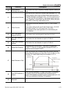
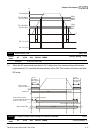
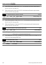
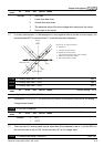
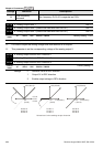
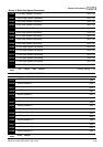
Settings 0 Zero bias
1 Lower than bias=bias
2 Greater than bias=bias
3 The absolute value of the bias voltage while serving as the center
4 Serve bias as the center
In a noisy environment, it is advantageous to use negative bias to provide a noise margin. It is
recommended NOT to use less than 1V to set the operation frequency.
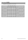
10V51234-1-2-3-4-5-10V 6 7 8 9
03-00
to
03-02
-6-7-8
-9
0
1
2
3
44
2
2
4
2
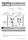
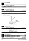
03-09~03-11 gain is positive
4
Zero bias
Lower than bias =bias
Greater than bias=bias
The absolute value of the bias voltage
while serving as the center
Serve bias as the center
bias
bias
Positive bias
Negative bias
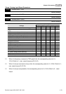
03-09 Analog Input Gain 1 (AVI) Unit: 1
03-10 Analog Input Gain 1 (ACI) Unit: 1
03-11 Analog Input Gain 1 (AUI) Unit: 1
Control
mode
VF VFPG SVC FOCPG TQRPG
Factory setting: 100.0
Settings -500.0~500.0%
Parameters 03-03 to 03-11 are used when the source of frequency command is the analog
voltage/current signal.
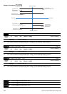
03-12 ACI/AVI2 Selection
Control
mode
VF VFPG SVC FOCPG TQRPG
Factory setting: 0
Settings 0 ACI
1 AVI 2
There are two AVI analog inputs can be used when this parameter is set to 1 and the SW2 on
the control board is set to AVI2. At this moment, ACI is for voltage input.
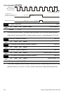
03-13 Analog Input Delay Time (AVI) Unit: 0.01