


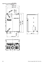

Appendix B Accessories|
Revision August 2008, 03VE, SW V2.04 B-3
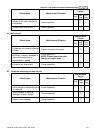
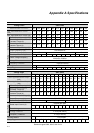
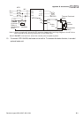
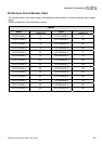
R/L1
S/L2
T/L3
NFB
MC
VFD Series
MOTOR
O.L.
U/T1
V/T2
W/T3
+P
-N
()
()
B1
B2
SA
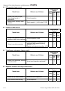
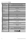
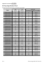
R/L1
S/L2
T/L3
MC
IM
BR
O.L.
Thermal
Overload
Relay or
temperature
switch
Surge
Absorber
Thermal Overload
Relay
Brake
Resistor
Brake
Unit
+P
-N
()
()
Note1: When using the AC drive with DC reactor, please refer to wiring diagram in the AC drive
user manual for the wiring of terminal +(P) of Brake unit.
Note2: wire terminal -(N) to the neutral point of power system.
Do NOT
Temperature
Switch
10. For model VFD110V43B, the brake unit is built-in. To increase the brake function, it can add
optional brake unit.