


Chapter 4 Parameters|
Revision August 2008, 03VE, SW V2.04 4-79
Group 3 Analog Input/Output Parameters
03-00
Analog Input 1 (AVI)
Factory Setting: 1
03-01 Analog Input 2 (ACI)
Factory Setting: 0
03-02 Analog Input 3 (AUI)
Factory Setting: 0
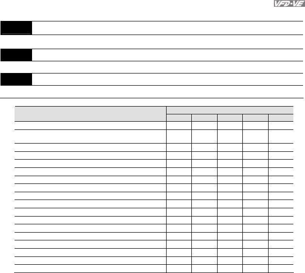
Control Mode
Settings
VF VFPG SVC FOCPG TQRPG
0: No function
○ ○ ○ ○ ○
1: Frequency command (torque limit under TQR control
mode)
○ ○ ○ ○ ○
2: torque command (torque limit under speed mode)
○
3: Torque compensation command
○ ○ ○ ○ ○
4: PID target value (refer to group 8)
○ ○ ○ ○
5: PID feedback signal (refer to group 8)
○ ○ ○ ○
6: P.T.C. thermistor input value
○ ○ ○ ○ ○
7: Positive torque limit
○
8: Negative torque limit
○
9: Regenerative torque limit
○
10: Positive/negative torque limit
○
11: PID feedback signal of tension
○ ○ ○ ○ ○
12: Line speed
○ ○ ○ ○ ○
13: Reel diameter
○ ○ ○ ○ ○
14: PID target value of tension (tension closed-loop)
○ ○ ○ ○ ○
15: Tension setting (tension open-loop)
○
16: Zero-speed tension
○
17: Tension taper
○
When it is frequency command or TQR speed limit, the corresponding value for 0~±
10V/4~20mA is 0 – max. output frequency(Pr.01-00)
When it is torque command or torque limit, the corresponding value for 0~±10V/4~20mA is 0 –
max. output torque (Pr.07-22).
When it is torque compensation, the corresponding value for 0~±10V/4~20mA is 0 – rated
torque.