


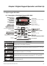
Chapter 2 Installation and Wiring|
2-12 Revision August 2008, 03VE, SW V2.04
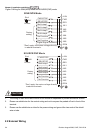
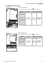
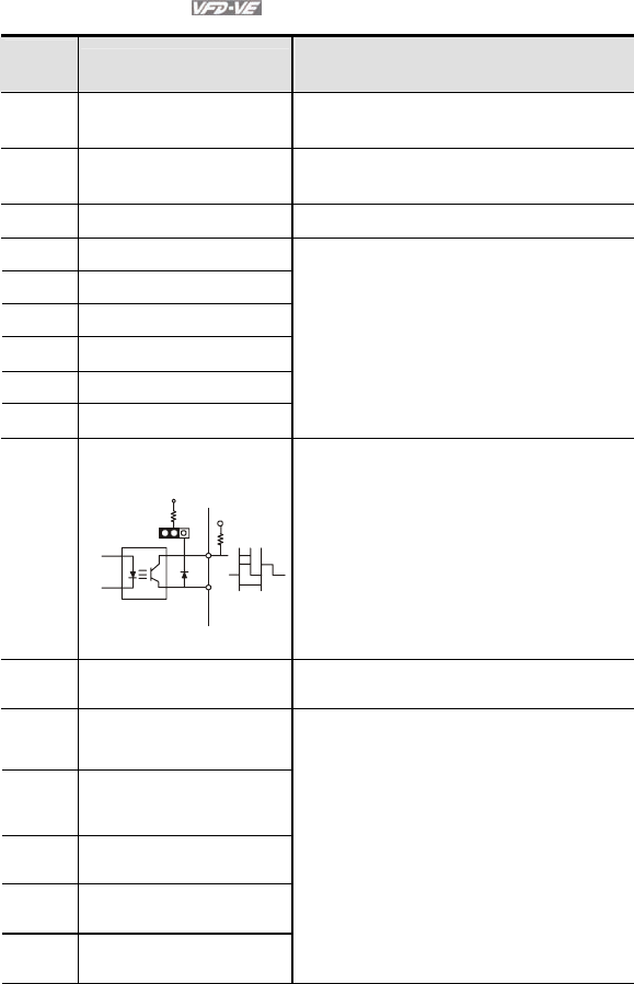
Terminal symbols and functions
Terminal
Symbol
Terminal Function
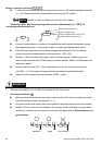
Factory Settings (SINK)
ON: Connect to DCM
FWD Forward-Stop Command
ON: Run in FWD direction
OFF: Stop acc. to Stop Method
REV Reverse-Stop Command
ON: Run in REV direction
OFF: Stop acc. to Stop Method
+24V DC Voltage Source +24VDC, 80mA, used for SOURCE mode.
MI1 Multi-function Input 1
MI2 Multi-function Input 2
MI3 Multi-function Input 3
MI4 Multi-function Input 4
MI5 Multi-function Input 5
MI6 Multi-function Input 6
Refer to Pr.02-01 to Pr.02-06 for programming
the Multi-function Inputs.
ON: the activation current is 6.5mA. OFF:
leakage current tolerance is 10μA.
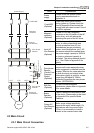
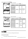
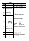
DFM
Digital Frequency Meter
(Open Collector Output)
Max: 48V
50mA
DFM-DCM
100%
50%
J5
internal circuit
Pulse voltage output monitor signal,
proportional to output frequency
Duty-cycle: 50%
Ratio: Pr.02-18
Min. load: 4.7kΩ
Max. current: 50mA
Max. voltage: 48Vdc
Jumper: DFM jumper, factory
setting is OC
DCM Digital Signal Common
Common for digital inputs and used for SINK
mode.
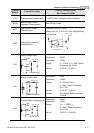
RA
Multi-function Relay Output 1
(N.O.) a
RB
Multi-function Relay Output 1
(N.C.) b
RC Multi-function Relay Common
MRA
Multi-function Relay Output 2
(N.O.) a
MRC Multi-function Relay Common
Resistive Load:
5A(N.O.)/3A(N.C.) 240VAC
5A(N.O.)/3A(N.C.) 24VDC
Inductive Load:
1.5A(N.O.)/0.5A(N.C.) 240VAC
1.5A(N.O.)/0.5A(N.C.) 24VDC
To output monitor signal, including in operation,
frequency arrival, overload and etc.
Refer to Pr.02-11~02-12 for programming