


Chapter 4 Parameters|
Revision August 2008, 03VE, SW V2.04 4-89
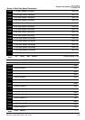
05-06 Rotor Resistance R1 of Motor 1 Unit: 0.001
05-07
Rr of Motor 1
Unit: 0.001
Control
mode
SVC FOCPG TQRPG
Factory setting: #.###
Settings
0~65.535Ω
05-08 Lm of Motor 1 Unit: 0.1
05-09 Lx of Motor 1 Unit: 0.1
Control
mode
SVC FOCPG TQRPG
Factory setting: #.#
Settings 0~6553.5mH
05-10 Motor 1/Motor 2 Selection
Control
mode
VF VFPG SVC FOCPG TQRPG
Factory setting: 1
Settings 1 Motor 1
2 Motor 2
It is used to set the motor that driven by the AC motor drive.
05-11
Frequency for Y-connection/ Δ−connection Switch
Unit: 0.01
Control
mode
VF VFPG SVC FOCPG TQRPG
Factory setting: 60.00
Settings 0.00 to 600.00Hz
05-12
Y-connection /Δ−connection Switch
Control
mode
VF VFPG SVC FOCPG TQRPG
Factory setting: 0
Settings 0 Disable
1 Enable
05-30
Delay Time for Y-connection/Δ −connection
Unit: 0.001
Control
mode
VF VFPG SVC FOCPG
Factory setting: 0.200
Settings 0 to 60.000
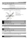
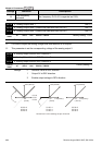
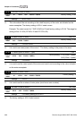
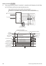
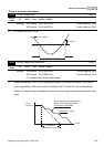
Pr.05-12 is used to enable/disable Y-connection/ Δ−connection Switch.
When Pr.05-12 is set to 1, the drive will select by Pr.05-11 setting and current motor frequency
to switch motor to Y-connection or Δ−connection. AT the same time, it will also affect motor
parameters (Pr.05-01 to 05-10/Pr.05-13 to Pr.05-21).
Pr.05-30 is used to set the switch delay time of Y-connection/Δ −connection.