


Chapter 4 Parameters|
4-76 Revision August 2008, 03VE, SW V2.04
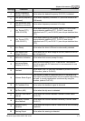
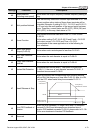
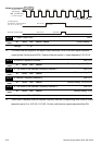
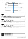
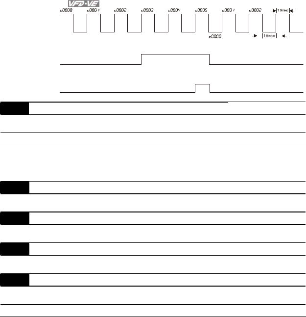
TRG
[00-04=01]
02-13=18
02-14=17
02-16=5
02-17=3
[02-06=23]
Display value
Counter Trigger
(output signal)
Preliminary Counter Value
(Pr.02-11 ~Pr.02-14)
Terminal Counter Value
The width of trigger signal
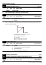
02-18 Digital Output Gain Unit:1
Control
mode
VF VFPG SVC FOCPG TQRPG
Factory setting: 1
Settings 1 ~ 40
It is used to set the signal for the digital output terminals (DFM-DCM) and digital frequency
output (pulse X work period=50%). Output pulse per second = output frequency X Pr.02-18.
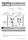
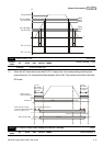
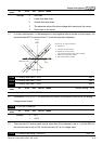
02-19 Desired Frequency Attained 1 Unit: 0.01
Control
mode
VF VFPG SVC FOCPG
Factory setting: 60.00/50.00
02-20 The Width of the Desired Frequency Attained 1 Unit: 0.01
Control
mode
VF VFPG SVC FOCPG
Factory setting: 2.00
02-21 Desired Frequency Attained 2 Unit: 0.01
Control
mode
VF VFPG SVC FOCPG
Factory setting: 60.00/50.00
02-22 The Width of the Desired Frequency Attained 2 Unit: 0.01
Control
mode
VF VFPG SVC FOCPG
Factory setting: 2.00
Settings 0.00 ~ 600.00Hz
Once output frequency reaches desired frequency and the corresponding multi-function output
terminal is set to 3 or 4 (Pr.02-11~Pr.02-14), this multi-function output terminal will be ON.