


Chapter 4 Parameters|
Revision August 2008, 03VE, SW V2.04 4-55
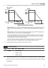
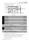
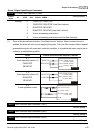
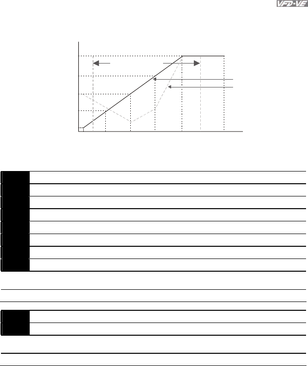
min. frequency, it will run with lower limit frequency. The upper limit frequency should be set to
be higher than the lower limit frequency.
01-05 01-03 01-01
01-06
01-04
01-02
01-0001-07
01-08
01-09
01-11
01-10
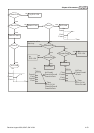
1st Output
Voltage Setting 1
Output Frequency
Lower Limit
Frequency output
ranges limitation
Regular V/f Curve
Special V/f Curve
Voltage
4th Freq.
Start Freq.
3rd Freq.
2nd Freq.
1st Freq.
Maximum Output
Frequency
V
/f Curve
2nd Output
Voltage Setting 1
3rd Output
Voltage Setting 1
4th Output
Voltage Setting 1
Output Frequency
Upper Limit
Frequency
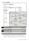
01-12 Accel. Time 1 Unit: 0.1/0.01
01-13 Decel. Time 1 Unit: 0.1/0.01
01-14 Accel. Time 2 Unit: 0.1/0.01
01-15 Decel. Time 2 Unit: 0.1/0.01
01-16 Accel. Time 3 Unit: 0.1/0.01
01-17 Decel. Time 3 Unit: 0.1/0.01
01-18 Accel. Time 4 Unit: 0.1/0.01
01-19 Decel. Time 4 Unit: 0.1/0.01
Control
mode
VF VFPG SVC FOCPG
Factory Setting: 10.00/10.0
Settings 0.00~600.00 sec/0.00~6000.0 sec
01-20 JOG Acceleration Time Unit: 0.1/0.01
01-21 JOG Deceleration Time Unit: 0.1/0.01
Control
mode
VF VFPG SVC FOCPG
Factory Setting: 1.00/1.0
Settings 0.00~600.00 sec/0.00~6000.0 sec
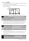
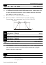
The Acceleration Time is used to determine the time required for the AC motor drive to ramp
from 0Hz to Maximum Output Frequency (Pr.01-00).
The Deceleration Time is used to determine the time require for the AC motor drive to
decelerate from the Maximum Output Frequency (Pr.01-00) down to 0Hz.
The Acceleration/Deceleration Time is invalid when using Pr.00-13 Optimal
Acceleration/Deceleration Setting.