


Chapter 4 Parameters|
4-120 Revision August 2008, 03VE, SW V2.04
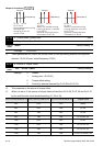
08-03 Derivative Control (D) Unit: 0.01
Control
mode
VF VFPG SVC FOCPG
Factory Setting: 0.00
Settings 0.00 to 1.00 sec
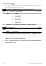
This parameter determines the damping effect for the PID feedback loop. If the differential time
is long, any oscillation will quickly subside. If the differential time is short, the oscillation will
subside slowly.
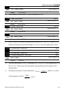
08-04 Upper limit for Integral Control Unit: 0.1
Control
mode
VF VFPG SVC FOCPG
Factory Setting: 100.0
Settings 0.0 to 100.0%
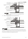
This parameter defines an upper bound or limit for the integral gain (I) and therefore limits the
Master Frequency.
The formula is: Integral upper bound = Maximum Output Frequency (Pr.01-00) x (Pr.08-04).
08-05 PID Output Frequency Limit Unit: 0.1
Control
mode
VF VFPG SVC FOCPG
Factory Setting: 100.0
Settings 0.0 to 110.0%
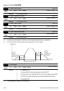
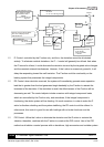
This parameter defines the percentage of output frequency limit during the PID control. The
formula is Output Frequency Limit = Maximum Output Frequency (Pr.01-00) X Pr.08-05 %.
This parameter will limit the Maximum Output Frequency.
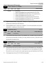
08-06 PID Offset Unit: 0.1
Control
mode
VF VFPG SVC FOCPG
Factory Setting: 0.0
Settings -100.0 to 100.0%
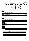
08-07 PID Delay Time Unit: 0.1
Control
mode
VF VFPG SVC FOCPG
Factory Setting: 0.0
Settings 0.0 to 2.5 sec