


Chapter 4 Parameters|
4-140 Revision August 2008, 03VE, SW V2.04
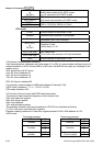
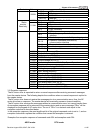
DATA (n-1)
to
DATA 0
Contents of data:
Nx8-bit data consist of 2n ASCII codes
n<=16, maximum of 32 ASCII codes
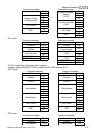
LRC CHK Hi
LRC CHK Lo
LRC check sum:
8-bit check sum consists of 2 ASCII codes
END Hi
END Lo
End characters:
END1= CR (0DH), END0= LF(0AH)
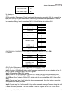
RTU mode:
START A silent interval of more than 10 ms
Address Communication address: 8-bit address
Function
Command code: 8-bit command
DATA (n-1)
to
DATA 0
Contents of data:
n×8-bit data, n<=16
CRC CHK Low
CRC CHK High
CRC check sum:
16-bit check sum consists of 2 8-bit characters
END A silent interval of more than 10 ms
3.2 Address (Communication Address)
Valid communication addresses are in the range of 0 to 254. A communication address equal to 0,
means broadcast to all AC drives (AMD). In this case, the AMD will not reply any message to the
master device.
00H: broadcast to all AC drives
01H: AC drive of address 01
0FH: AC drive of address 15
10H: AC drive of address 16
:
FEH: AC drive of address 254
For example, communication to AMD with address 16 decimal (10H):
ASCII mode: Address=’1’,’0’ => ‘1’=31H, ‘0’=30H
RTU mode: Address=10H
3.3 Function (Function code) and DATA (data characters)
The format of data characters depends on the function code.
03H: read data from register
06H: write single register
08H: loop detection
10H: write multiple registers
The available function codes and examples for VFD-VE are described as follows:
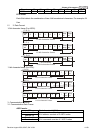
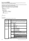
(1) 03H: multi read, read data from registers.
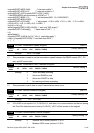
Example: reading continuous 2 data from register address 2102H, AMD address is 01H.
ASCII mode:
Command message: Response message:
STX ‘:’ STX ‘:’
‘0’ ‘0’
Address
‘1’
Address
‘1’
‘0’ ‘0’
Function
‘3’
Function
‘3’
‘2’ ‘0’ Starting data
address
‘1’
Number of data
(Count by byte)
‘4’