


Chapter 2 Installation and Wiring|
Revision August 2008, 03VE, SW V2.04 2-13
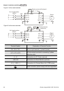
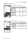
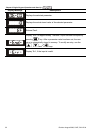
Terminal
Symbol
Terminal Function
Factory Settings (SINK)
ON: Connect to DCM
+10V Potentiometer Power Supply +10VDC 20mA (variable resistor 3-5kohm)
MCM
Multi-function Output
Common (Photocoupler)
Max. 48VDC 50mA
MO1
Multi-function Output 1
(Photocoupler)
MO2
Multi-function Output 2
(Photocoupler)
Maximum 48VDC, 50mA
Refer to Pr.02-13 to Pr.02-14 for programming
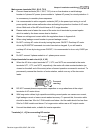
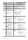
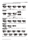
MO1~MO2-DCM
MO1~MO2
MCM
Internal Circuit
Max: 48Vdc
50mA
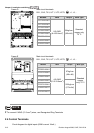
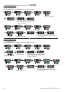
AVI
Analog voltage Input
ACM
AVI
+10V
internal circuit
AVI circuit
Impedance: 200kΩ
Resolution: 12 bits
Range: 0 ~ 10VDC = 0 ~ Max. Output
Frequency (Pr.01-00)
Set-up: Pr.03-00 ~ Pr.03-02
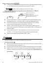
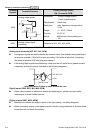
ACI
Analog current Input
ACM
ACI
internal circuit
ACI circuit
Impedance: 250Ω
Resolution: 12 bits
Range: 4 ~ 20mA/0~10V =
0 ~ Max. Output Frequency
(Pr.01-00)
Set-up: Pr.03-00 ~ Pr.03-02
Jumper: ACI jumper, factory setting is
4-20mA
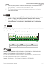
AUI
Auxiliary analog voltage input
ACM
AUI
+10
~
-10V
internal circuit
AUI circuit
Impedance: 200kΩ
Resolution: 12 bits
Range: -10 ~ +10VDC =
0 ~ Max. Output Frequency
(Pr.01-00)
Set-up: Pr.03-00 ~ Pr.03-02