


Modbus Communications - RTU Framing
Liebert
®
IntelliSlot
®
Modbus/BACnet IP 6
2.3.2 Function Code
The function code field tells the addressed slaves what function to perform. Function codes are
designed to invoke a specific action by the slave device. The function code ranges from 1 to 127.
Liebert IntelliSlot
®
Modbus server supports the following Modbus function codes.
2.3.3 Data Fields
The data field length varies, depending on whether the message is a request or a response to a packet.
This field typically contains information required by the slave device to perform the command
specified or to the response to a data request from the master device.
2.3.4 Error Check Field
The Error Check Field consists of a 16-bit (2 byte) Cyclical Redundancy Check (CRC16). It allows the
receiving device to detect a packet that has been corrupted by transmission errors.
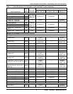
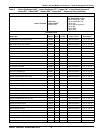
2.4 RTU Framing
The example below shows a typical query and response from a Liebert IntelliSlot interface card. The
master device initiates a query asking Slave Device, with address 2, for holding registers starting at
holding register 40051 (offset 50) and including next two registers (three total).
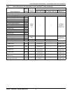
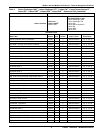
Slave Device, with address 2, responds to Function Code 3 with 6 bytes of hexadecimal data and ends
with CRC16 checksum.
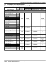
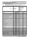
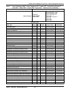
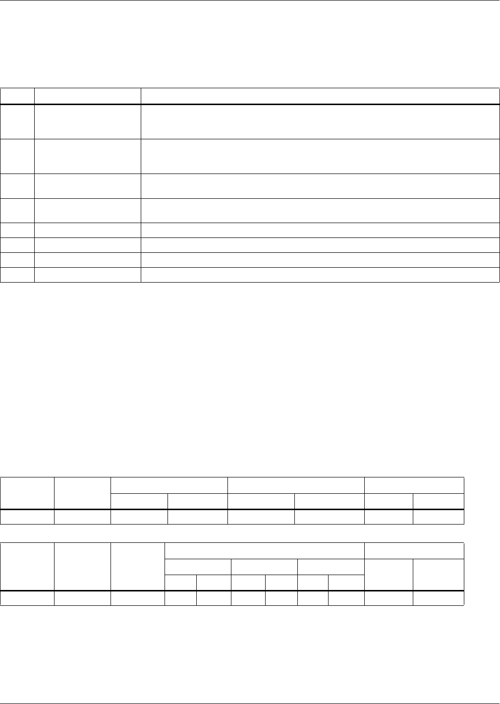
Table 3 Supported Modbus function codes
Code Function Description
01 Read Coils
Read from 1 to 2000 contiguous status of coils managed by the server. Coils in the
response message are packed as one per bit of a byte, 1=On and 0=Off. If the requested
quantity of coils is not a multiple of 8, zeros are padded in the final byte.
02 Read Discrete Inputs
Read from 1 to 2000 contiguous input status managed by the server. Discrete inputs in
the response message are packed as one per bit of a byte, 1=On and 0=Off. If the
requested number of inputs is not a multiple of 8, zeros are padded in the final byte.
03 Read Holding Registers
Read the contents of contiguous block of 1 to 127 holding registers. Data are packed as
two bytes per register; the first byte contains the high order bits.
04 Read Input Registers
Read the contents of contiguous block of 1 to 127 Input registers. Data are packed as
two bytes per register; the first byte contains the high order bits.
05 Write Single Coil Write a single output to either On (1) or Off (0) mapped in coil section.
06 Write Single Register Write a value into a single holding register;
15 Write Multiple Coils Force each coil in a sequence of coils to either On or Off.
16 Write Multiple Registers Write values into a block of contiguous registers (1 to 120)
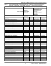
Table 4 Query sample
Slave
Address
Function
Code
Starting Register Number of Registers CRC16
Hi Byte Lo Byte Hi Byte Lo Byte Hi Byte Lo Byte
02 03 00 32 00 03 E5 FA
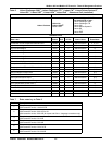
Table 5 Response sample
Slave
Address
Function
Code
Count:
Bytes of
Data
Register CRC16
40051 Data 40052 Data 40053 Data
Hi Byte Lo ByteHi Lo Hi Lo Hi Lo
02 03 6 1 58 00 FA 00 54 1B 0D
Register values: 40051 = 158 (hex) = 344 (decimal)
40052 = FA (hex) = 250 (decimal)
40053 = 54 (hex) = 84 (decimal)