


BACnet Communications - UPS Systems
361 Liebert
®
IntelliSlot
®
Modbus/BACnet IP
Sum of MMS Output RMS Currents
for Phase A
The sum of the multi-module system output RMS currents for phase A
Sum of MMS Output RMS Currents
for Phase B
The sum of the multi-module system output RMS currents for phase B
Sum of MMS Output RMS Currents
for Phase C
The sum of the multi-module system output RMS currents for phase C
System Breaker(s) Close Failure One or more breakers in the system failed to close
System Breaker(s) Open Failure One or more breakers in the system failed to open
System Controller Error System controller internal error
System Date and Time The system date and time
System Fan Capacity Status System fan capacity status
System Fan Failure - Redundant Redundant system fan failure
System Fan Redundant Status System fan redundant status
System Fan Status System fan status
System Input Current Imbalance System Input Currents are Imbalanced
System Input Current Limit The RMS input current has reached the input current limit threshold
System Input Frequency The system input frequency
System Input Nominal Frequency The nominal (or rated) system input frequency
System Input Nominal Voltage The nominal (or rated) system input voltage
System Input Phs Rotation Error
The power conductors on the input line are not wired to the UPS in the sequence
preferred for the rectifier (A-B-C)
System Input Power Problem The input is not qualified to provide power to the system
System Input Power Source System input power source
System Input RMS A-B The System Input RMS Voltage between Phase A and Phase B
System Input RMS B-C The System Input RMS Voltage between Phase B and Phase C
System Input RMS C-A The System Input RMS Voltage between Phase C and Phase A
System Input RMS Current Phase A The system input RMS current for Phase A
System Input RMS Current Phase B The system input RMS current for Phase B
System Input RMS Current Phase C The system input RMS current for Phase C
System Isolation Output Breaker System isolation output breaker
System Load Bank Breaker System load bank breaker
System Output Apparent Power The sum total apparent power of all system output phases
System Output Breaker System output breaker
System Output Fault A fault has been detected in the system output
System Output Frequency The system output frequency
System Output Low Power Factor The system output power factor is low, resulting in reduced output capacity
System Output Maximum Amp Rating System output maximum amperage rating
System Output Nominal Frequency The nominal (or rated) system output frequency
System Output Nominal Voltage The nominal (or rated) system output voltage
System Output Pct Power Phase A The system output power on phase A as a percentage of the rated capacity
System Output Pct Power Phase B The system output power on phase B as a percentage of the rated capacity
System Output Pct Power Phase C The system output power on phase C as a percentage of the rated capacity
System Output Pct Pwr (VA) Phs A
The system output apparent power on phase A as a percentage of the rated
capacity
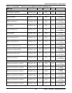
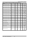
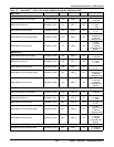
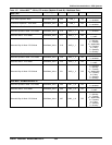
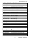
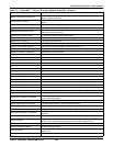
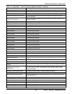
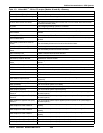
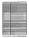
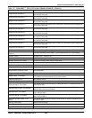
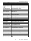
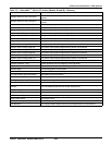
Table 113 Liebert NXL
™
- 50 Hz, CE version (Models 48 and 49)—Glossary
Data Label Data Description