


Modbus 485 and Modbus IP Protocols - Thermal Management Products
43 Liebert
®
IntelliSlot
®
Modbus/BACnet IP
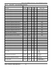
Fan Control Sensor 30463 40463 1 —
0 = Supply
1 = Remote
2 = Return
Remote Sensor Function Module Index 1 30464 40464 1 —
0 = Disable
1 = Reference
2 = Control
Remote Sensor Function Module Index 2 30465 40465 1 —
0 = Disable
1 = Reference
2 = Control
Remote Sensor Function Module Index 3 30466 40466 1 —
0 = Disable
1 = Reference
2 = Control
Remote Sensor Function Module Index 4 30467 40467 1 —
0 = Disable
1 = Reference
2 = Control
Remote Sensor Function Module Index 5 30468 40468 1 —
0 = Disable
1 = Reference
2 = Control
Remote Sensor Function Module Index 6 30469 40469 1 —
0 = Disable
1 = Reference
2 = Control
Remote Sensor Function Module Index 7 30470 40470 1 —
0 = Disable
1 = Reference
2 = Control
Remote Sensor Function Module Index 8 30471 40471 1 —
0 = Disable
1 = Reference
2 = Control
Remote Sensor Function Module Index 9 30472 40472 1 —
0 = Disable
1 = Reference
2 = Control
Remote Sensor Function Module Index 10 30473 40473 1 —
0 = Disable
1 = Reference
2 = Control
System Status 30474 — 1 —
1 = Normal Operation
2 = Startup
8 = Normal with Warning
16 = Normal with Alarm
32 = Abnormal Operation
System Operating State 30475 — 1 —
0 = Off / 1 = On
2 = Standby
System Control Mode 30476 — 1 —
0 = Internal (Auto)
1 = External (Manual)
System Operating State Reason 30477 — 1 —
0 = Reason Unknown
1 = Network Display
2 = Alarm
3 = Schedule
4 = Remote System
5 = External Input
6 = Local Display
System On/Off Control 30478 40478 1 — 0 = Off / 1 = On
Condenser Low Noise Mode State 30490 — 1 —
0 = Inactive
1 = Active (Interval)
2 = Active (Full Day)
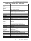
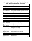
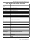
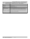
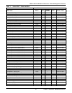
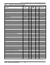
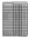
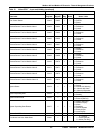
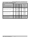
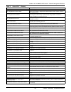
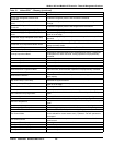
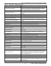
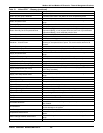
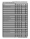
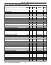
Table 12 Liebert CRV
™
- Input and Holding (continued)
Controller Liebert iCOM
®
v4
Data Label
Input
Register
Holding
Register
# of
Reg. Scale Notes / Units