


DFX-8500
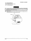
3.2.4 Circuit Boards Removal
This section describes how to remove the circuit boards.
3.2.4.1 Bottom Panel Assembly Removal
0 /f is best to remove the top cover before you tilt back the DrintW as described in the steos below
Refer to section 3.2.3.7 for instructions on removing the top Cover.
E3
tf you tin back the printer with the top cover attached, be careful not to put too much weight on the toI
cover or any other printer components.
U
Spread a thick, soft cloth under the printer before you follow the steps below
U When you attech the bottom panel, make sure the parallel interface cable latch is not caughi
between the lower case and bottom panel.
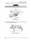
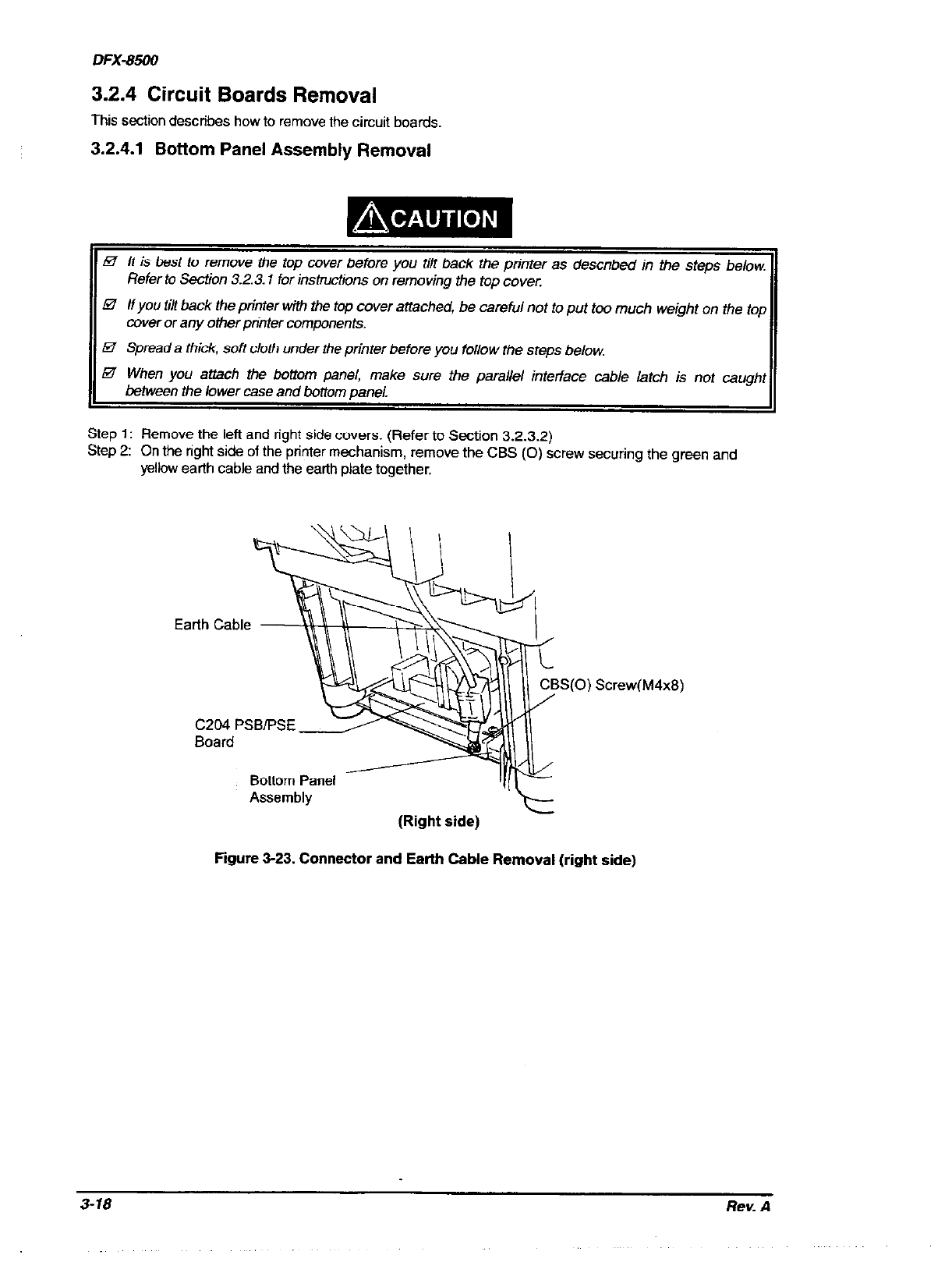
Step 1: Remove the left and right side covers. (Refer to Section 3.2.3.2)
Step 2:
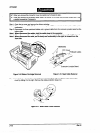
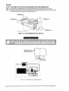
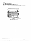
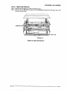
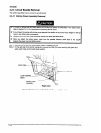
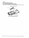
On the right side of the printer mechanism, remove the CBS (0) screw securing the green and
yellow earth cable and the earth plate together.
Earth Cable
S(0) Screw(M4x8)
CL’04 PSB/PSE
Board
Bottom Panel
Assembly
(Right side)
Figure 3-23. Connector and Earth Cable Removal (right side)
3-18
Rev. A