DISASSEMBLY AND ASSEMBLY
3.2.6.14 PG Home Sensor Removal
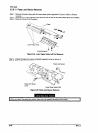
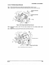
Step 1: Remove the frontlrear tractor select lever assembly. (Refer to Section 3.2.6.2)
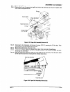
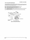
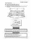
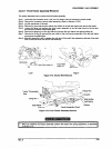
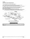
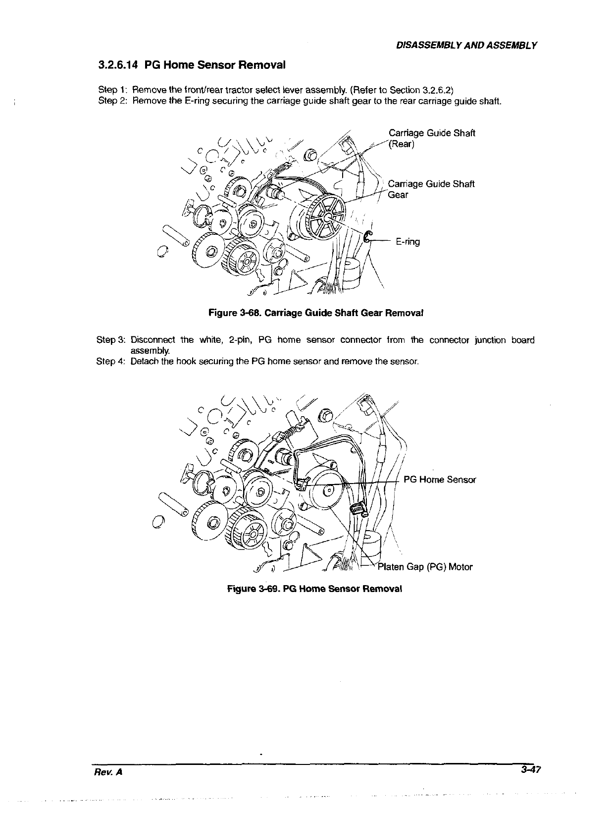
Step 2: Remove the E-ring securing the carriage guide shaft gear to the rear carriage guide shaft.
Carriage Guide Shaft
Carriage Guide Shaft
Figure 3-68. Carriage Guide Shaft Gear Removal
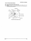
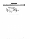
Step3: Diiconnect the whiie, 2-p% PG home sensor connector from the connector junction board
assembly.
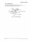
Step 4:
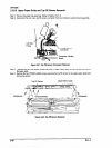
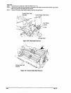
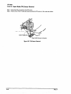
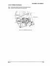
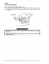
Detach the hook securing the PG home sensor and remove the sensor.
PG Home Sensor
laten Gap (PG) Motor
Figure 3-89. PG Home Sensor Removal
Rev. A 3-47


