


DFX-8500
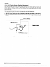
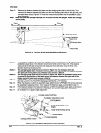
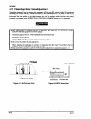
Step 12:
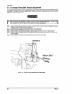
Measure the distance between the platen and the carriage guide shaft on the left side. Then
measure the distance between the platen and the rear carriage guide shaft on the right side, and
compare these values.(Figure4-11 shows the measurement position and the parallelism adjust
lever operation.)
Note: When you shift the carriage manually, do not touch the both dialgauges. Rotate the carriage
motor pulley.
t
7Omm+
+70mm
FRight Side Frame
Figure 4-11. Carriage Guide Shaft Parallelism Adjusbnent
Step 13:
Notes 1:
Notes 2:
Step 14:
Step 15:
Step 16:
step 17:
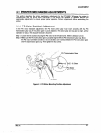
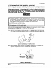
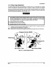
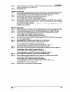
ii the distance measured at the left side is greater than that measured at the right side, move the
parallelism adjust fever in the direction shown by the white arrow in Figure 4-9. If the distance
measured at the left side is less than that measured at the right side, move the lever in the
direction shown by the black arrow.
The carriage guide shaft moves as shown in Figure 4-8. For example, when the
parallelism adjust lever is moved in the directon of the black arrow, the distance between
the right side of the platen and printhead nose namws a little bit.
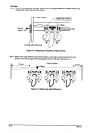
The carriage guide shaft moves as shown in Figure 4-E. When the paralkiism adjust lever
is moved in the direction of the black anow, the distance between the right side of the
platen and print head nose narrows a little bit.
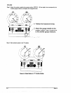
Repeat steps 11 and 12 until the distance between the distance measured at the two positions is
less than 2 0.015 mm.(The #F610 diil gauge matches the 2 “15’ notches.)
When the distance is within the specified range, tighten the two CP(PS)(M4 X 6) screws securing
the parallelism adjustment lever. Then measure the distances again, as described in step 11.
If the distance between the measured distances is within the specffii range, apply screw lock to
the two screws.(Refer to Section 6.2 for fubrfcation and adhesive application instructions.)
Go to Section 4.1.6 platen angle adjustment.
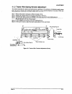
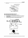
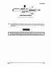
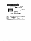
Carriage Guide Shafl Rear
arallelism Adjustment Lever
Guide Shaft Holder Lever
Guide Shafl Holding Spring
Figure 4-12. Parallelism Adjustment Lever Operation