


DISASSEMBLY AND ASSEMBLY
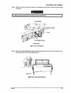
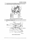
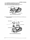
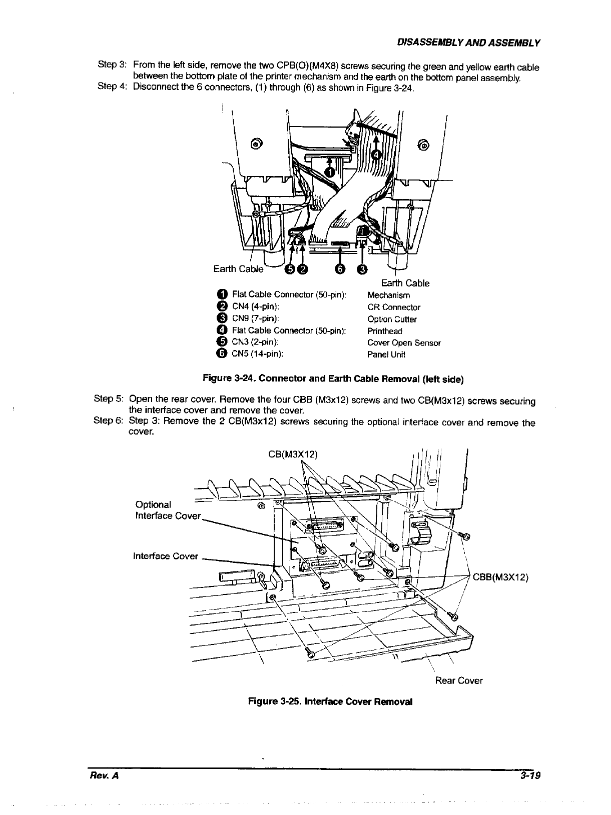
From the left side, remove the two CPB(O)(M4X6) screws securing the green and yellow earth cable
between the bottom plate of the printer mechanism and the earth on the bottom panel assembly.
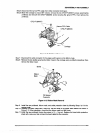
Disconnect the 6 connectors, (1) through (6) as show” in Figure 3-24.
Step 3:
Step 4:
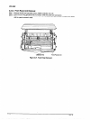
Earth Cable
0 Flat Cable Connector (50pin):
Mechanism
@ CN4 (Cpin): CR Connector
@ CN9 (7-pin): Option cutter
0 Flat Cable Connector @-pin): Printhead
0 CN3 (Z-pin):
cover Open sensor
0 CN5 (14-pin): Pane1 unit
Figure 3-24. Connector and Earth Cable Removal (left side)
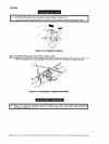
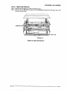
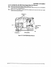
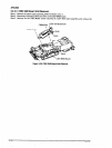
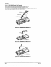
Step 5: Open the rear cover. Remove the four CBB (M3x12) screws and two CB(M3xlZ) screws securing
the interface cover and remove the cover.
Step 6: Step 3: Remove the 2 CB(M3x12) screws securing the optional interface cover and remove the
cover.
CB(M3X12)
dIlli/ I
Optional
Interface Cover
Interface Cover
CBB(M3X12)
Rear Cover
Rgure 3-25. Interface Cover Removal
Rev. A
3-19