


DFX-8SGQ
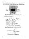
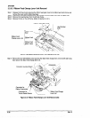
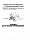
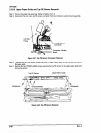
326.5 Connector Junction Board Assembly and FPC Board Assembly Removal
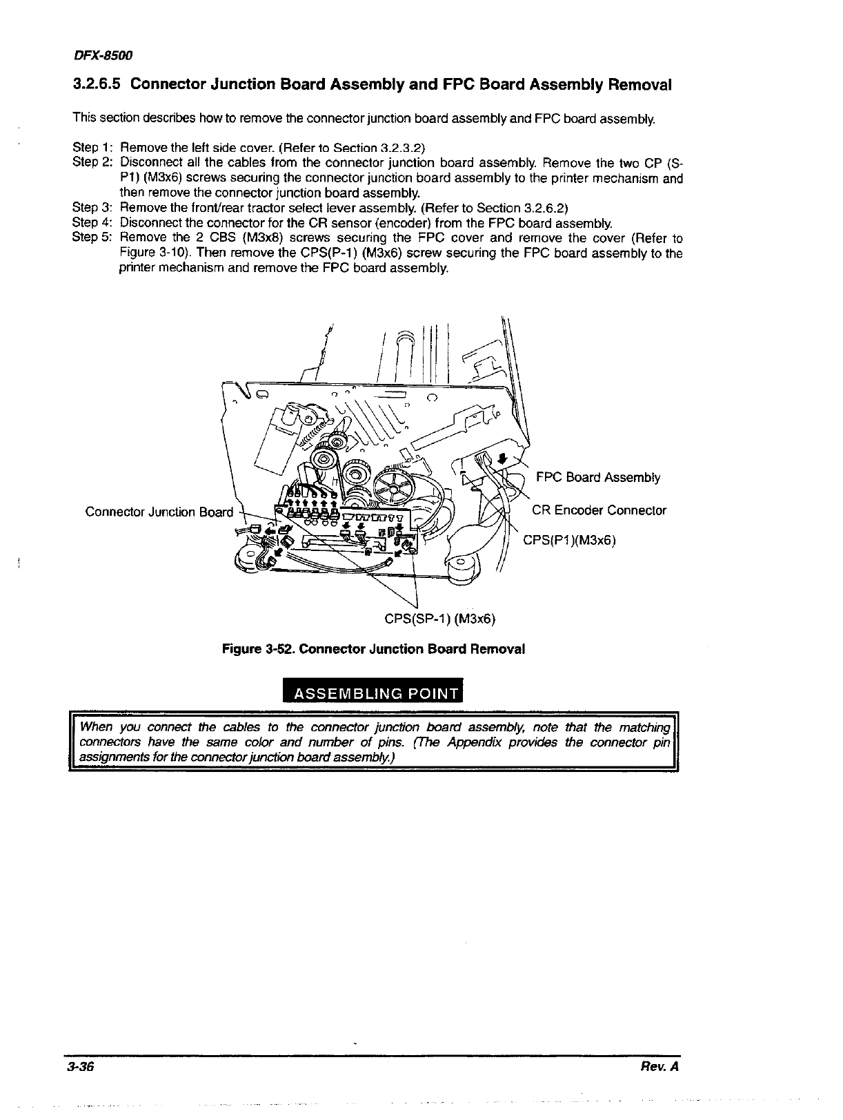
This section describes how to remove the connector junction board assembly and FPC board assembly.
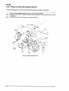
Step 1: Remove the left side cover. (Refer to Section 3.2.3.2)
Step 2: Disconnect all the cables from the connector junction board assembly. Remove the two CP (S-
Pl) (M3x6) screws securing the connector junction board assembly to the printer mechanism and
then remove the connector junction board assembly.
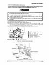
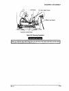
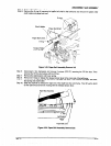
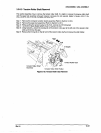
Step 3: Remove the front/rear tractor select lever assembly. (Refer to Section 3.2.6.2)
Step 4: Disconnect the connector for the CR sensor (encoder) from the FPC board assembly.
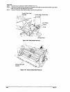
Step5: Remove the 2 CBS (M3x6) screws securing the FPC cover and remove the cover (Refer to
Figure 3-10). Then remove the CPS(P-1) (M3x6) screw securing the FPC board assembly to the
printer mechanism and remove the FPC board assembly.
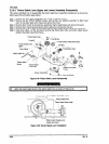
Connect01 Junction
FPC Board Assembly
CR Encoder Connector
CPS(SP-1) (M3x6)
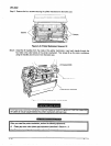
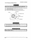
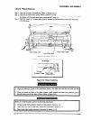
When you connect the cables to the connector junction
board assembly, note that the matching
connectors have the sane color and number of pins. (7he Appendix provides the connector pin
3-36
Rev. A