


OPERATING PRINCIPLES
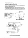
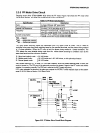
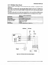
2.3.7 PG Motor Drive Circuit
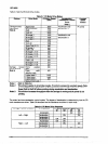
Figure 2-25 shows a block diagram of the PG motor drive circuit, and Table 2-11 provides PG motor
specifications.
The PG motor is a stepping motor. The motor phase switching signals are output from the E05B36 ports
PGA to PGD. The motor common voltage (PGCOM) alternates between drive mode (+37 VDC) and hold
mods (+5 VDC) using the PG H/R signal of E05B36. The phase driver circuit is made by discrete transistors
Q12 to a15
The phase A output pulse from the platen gap encoder (ENCA) is input to port ENCA of E05B36 and the
phase B output pulse from the platen gap encoder (ENCB) is input to port ENCB of E05B36. The E05B36
counts these pulses using the internal counter and determines the amount and direction of motor rotation.
Figure 2-25. PG Motor Drive Circuit Block Diagram
Rev. A
2-31