


CHAPTER 3
DISASSEMBLY AND ASSEMBLY
3.1 OVERVIEW
. . . . . . . . . . . . . . . . . . . . . . . . . . . . . . . . . . . . . . . . . . . . . . . . . . . . . . . . . . . . . . . . . . . . . . . . . . . . . . . . . . . . . . . . . . . . . . . . . . . . . . ...*..
3-1
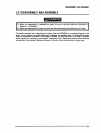
3.1.1 Precautions for Disassembly and
Assembly . . . . . . . . . . . . . . .._...................................................... 3-l
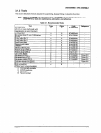
3.1.2 Tools . . . . . . . . . . . . . . . . . . . . . . . . . . . . . . . . . . . . . . . . . . . . . . . . . . . . . . . . . . . . . . . . . . . . . . . . . . . . . . . . . . . . . . . . . . . . . . . . . . . . . . . . . . . . . . . . . . . . . . . . ................
3-3
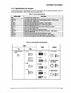
3.1.3 Specification for Screws . . . . . . . . . . . . . . . . . . . . . . . . . . . . . . . . . . . . . . . . . . . . . . . . . . . . . . . . . . . . . . . . . . . . . . . . . . . . . . . . . . . . . . . . . . . . . . . . . . . . . . . .
3-5
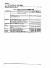
3.1.4 Service Checks After Repair
. . . . . . . . . . . . . . . . . . . . . . . . .._...................................................................... 3-8
3.2 DISASSEMBLY AND ASSEMBLY . . . . . . . . . . . . . . . . . . . . . . . . . . . . . . . . . . . . . . . . . . . . . . . . . . . . . . . . . . . . . . . . . . . . . . . . .
3-7
32.1 ROM Replacement . . . . . . . . . . . . . . . . . . . . . . . . . . . . . . . . . . . . . . . . . . . . . . . . . . . . . . . . . . . . . . . . . . . . . . . . . . . . . . . . . . . . . . . . . . . . . . . . . . . . . . . . . . . . . . . . . .
3-8
3.2.2 Printhead and Ribbon Mask
Assembly Removal . . . . . . . . . . . . . . . . . . . . . . . . . . . . . . . . . . . . . . . . . . . . . . . . . . . . . . . . . . . . . . . . 59
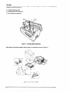
3.2.3 Housing Removal . . . . . . . . .._......................................................................................................
3-13
3.2.3.1 Top Cover Removal .__............_..__.........................................,......,............................ 3-13
3.2.3.2 Left, Right, and Front Covers Removal and Fuse Replacement ..___._____.___........... 3-14
3.2.3.3 Front Panel Unit Removal . . . . . . . .._........................................................................ 3-16
3.2.3.4 Upper Case Removal . . . . . . . . . . . . . ..__..........................................................................
3-17
3.2.4 Circuit Boards Removal . . . . . . . . . . . . . . . . . . . . . . . . . . . . . . . . . . . . . . . . . . . . . . . . . . . . . . . . . . . . . . . . . . . . . . . . . . . . . . . . . . . . . . . . . . . . . . . . . . . . . . .
3-18
324.1 Bottom Panel Assembly Removal ____.......___._..__.,.................................................... 3-18
3.2.4.2 Cooling Fan and C204 Power Supply Board Unit Removal _.__...,...._.._._._................ 521
3.2.4.3 C204 SUB Board Unit Removal ._.__._...........__................................................,......... 3-22
3.2.4.4 C204 DRV-B and C204 DRV Board Units Removal ..__._._._.__............................ 3-23
3.2.4.5 C204 MAIN Board Unit Removal __.,.._...__._.___._...,......................................,............. 3-24
3.2.4.6 AC Inlet Removal __,_.__._......_____.........................,....,..........,...,.................................. 3-26
3.2.4.7 C204 PNL Board Removal . .._____._..____....................................,................................. 3-27
32.5 Interlock Switch and Cover
Open Sensor Assembly Removal . . . . . . . . . . . . . . . . . . . . . . . . . . . . . . . . . . . . . . . . 3-28
3.2.6 Printer Mechanism Removal
. . . . . . . . . . . . . . . . . . . . . . . . . . . . . . . . . . . . . . . . . . . . . . . . . . . . . . . . . . . . . . . . . . . . . . . . . . . . . . . . . . . . . . . . . . . . . . . 3-29
3.2.6.1 Fan Removal _._..______.__...................................................................................,......... 3-31
3.2.6.2 Ribbon Feed Change Lever Unit Removal .._.____.___......_.......................................... 3-32
3.2.6.3 FmnifRear Tractor Select Lever Assembly Disassembly ..___..__............................. 3-34
3.2.6.4 Ribbon Jam Sensor Removal . . . . . . ..__........................................................................ 3-35
3.2.6.5 Connector Junction Board Assembly and FPC Board Assembly Removal .._..l...... 3-36
3.2.6.6 PG Sensor and PG Motor Removal _....__.____.____.__...................,......................,......... 3-37
3.2.6.7 Plunger and Paper Bail Assembly Removal ___...__.................................................... 3-38
3.2.6.8 Upper Paper Guide and Top PE Sensor Removal ..__.__.__.............................. 3-40
3.2.6.9 Tension Roller Shaft Removal ____..____..____.__..................................,...............,....,...... 3-41
3.2.6.10 Platen Removal ________........____.........................,.,..,.................,................................ 3-43
3.2.6.11 Paper Jam Sensor Removal _________......_.___...........,.................,..,............................. 3-44
3.2.6.12 Pull Tractor Sensor Removal ___.__._........_._...........,,................................................. 3-45
3.2.6.13 Paper Width (PW) Sensor Removal .._......_._................................................. 3-46
326.14 PG Home Sensor Removal . .._.._._...................................................................... 3-47
326.15 PF Motor Removal _____...........__._......................._..__......._...._.....____........................... 3-49
3.2.6.16 Left Side Frame Gear Removal _.____............__........................................................ 3-50
3.2.6.17 Front Tractor Assembly Removal _._._...................................................................... 3-51
3.2.6.18 Rear Tractor Assembly Removal __.............____......................,................................ 3-52
3.2.6.19 CR Motor Fan Removal . . .._._____________...................................................................... 3-53
3.2.6.20 CR Motor Removal _._.__._._._.................................................................................... 3-54
3.2.6.21 CR (Carriage Encoder) Sensor Removal .___,.__._...._._____......................................... 3-55
3.2.6.22 Carriage Mechanism Disassembly __._.._._._____.__......................,.....................,......... 3-56
3.2.6.23 Paper Guide Support Plate Removal __.__.._____.__,.....................,............................... 3-59